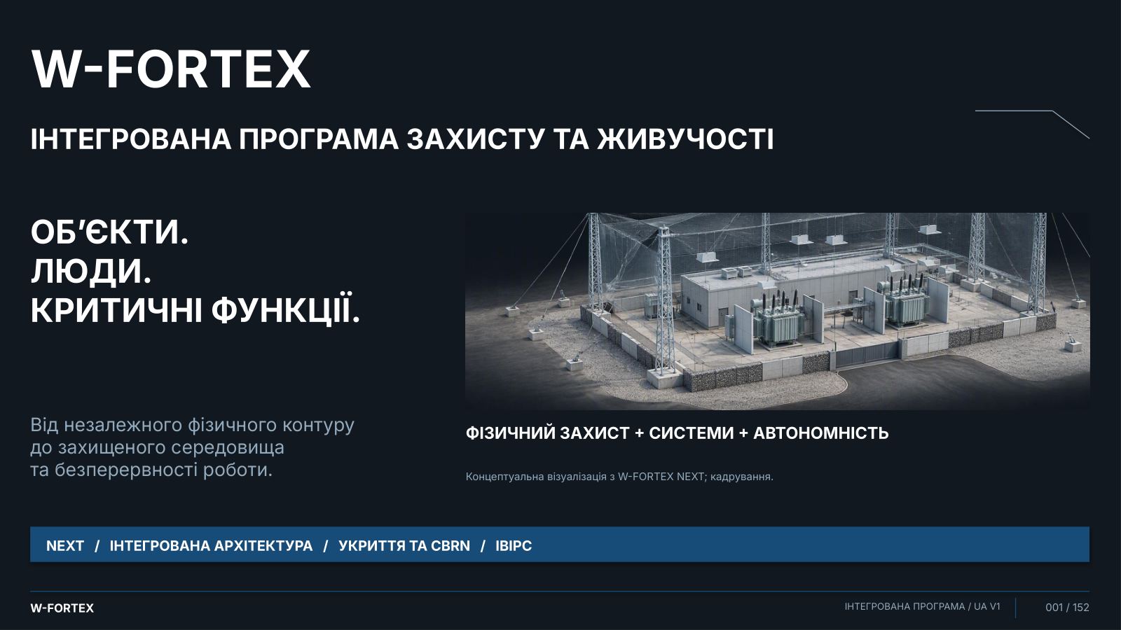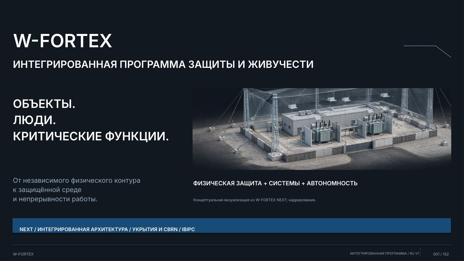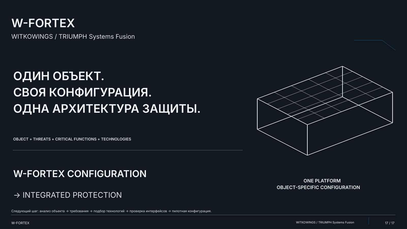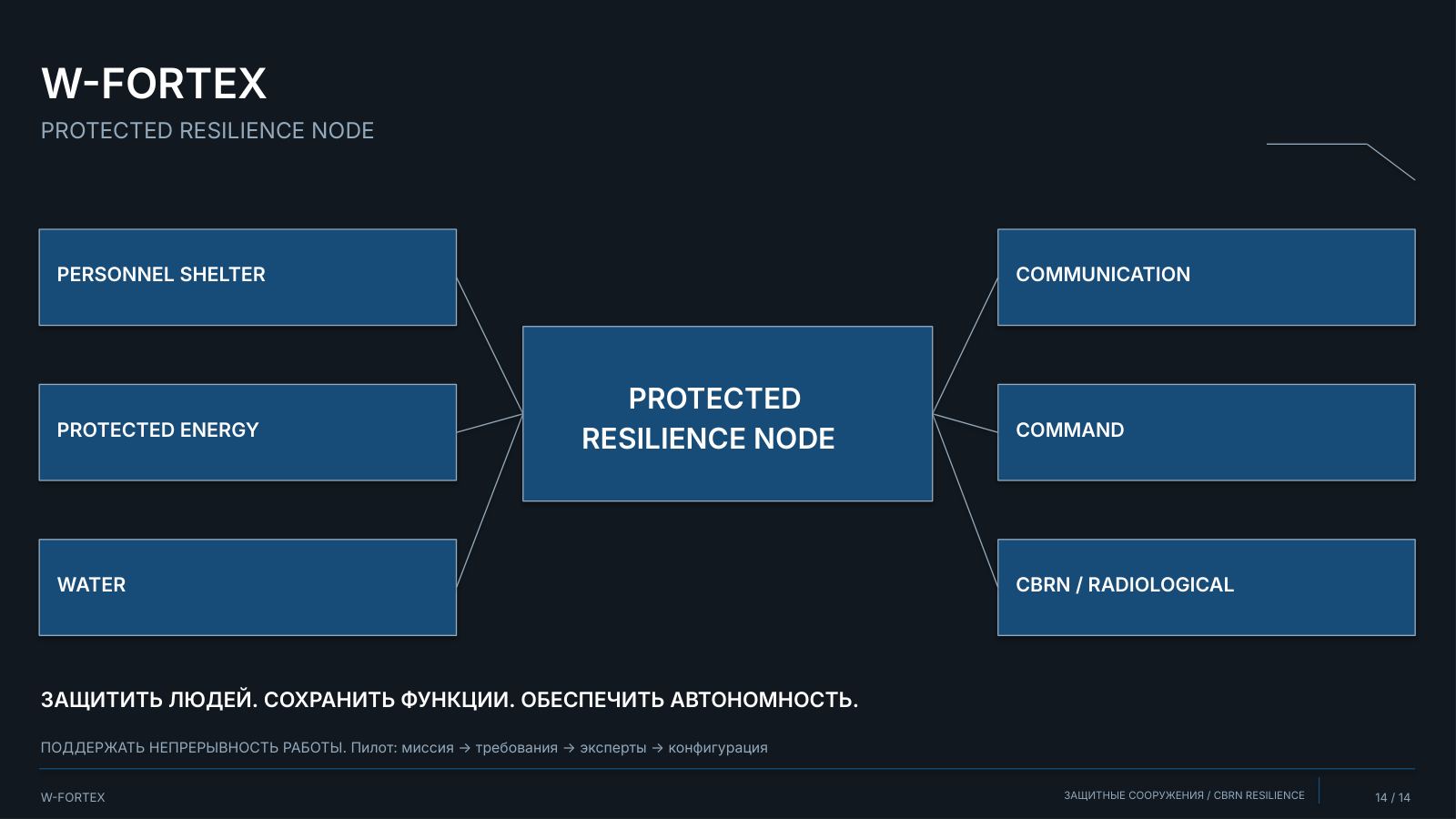
One Programme — Protecting Critical Functions
From facility requirements to protection, autonomy and a justified configuration. A map of the full programme: from the overall architecture to integration, protected functions and technical documents.
| Block | Title | Content | Slides |
|---|---|---|---|
| I | W-FORTEX NEXT | Physical architecture, modular layers, survivability | 04–22 |
| II | Integrated Protection Architecture | Function selection, coordination, interfaces, recovery | 23–40 |
| III | Shelters and CBRN Resilience | Protection of people, autonomy, specialised modes | 41–55 |
| IV | IBIPC — Technical Annex | Products, drawings, tests, primary documents | 56–151 |
Introduction — slides 01–03, overall closing slide — 152. Ranges include divider slides. The internal numbering of the sources has been preserved; overall navigation is provided by PDF bookmarks.
- I · W-FORTEX NEXT — Physical protection and survivability: independent perimeter, modular protective layers, localisation of consequences
- II · Integrated architecture — Selection and coordination of the required functions: detection and control, active / physical layers, response and recovery
- III · Shelters and CBRN — People and protected critical functions: life support, autonomous technical modules, specialised modes
- IV · IBIPC — Technologies and evidence base: products and structures, drawings and tests, limits of application
Facility-oriented configuration → pilot → integration verification. The programme concept is not certification. IBIPC evidence applies only to the relevant products and test conditions.
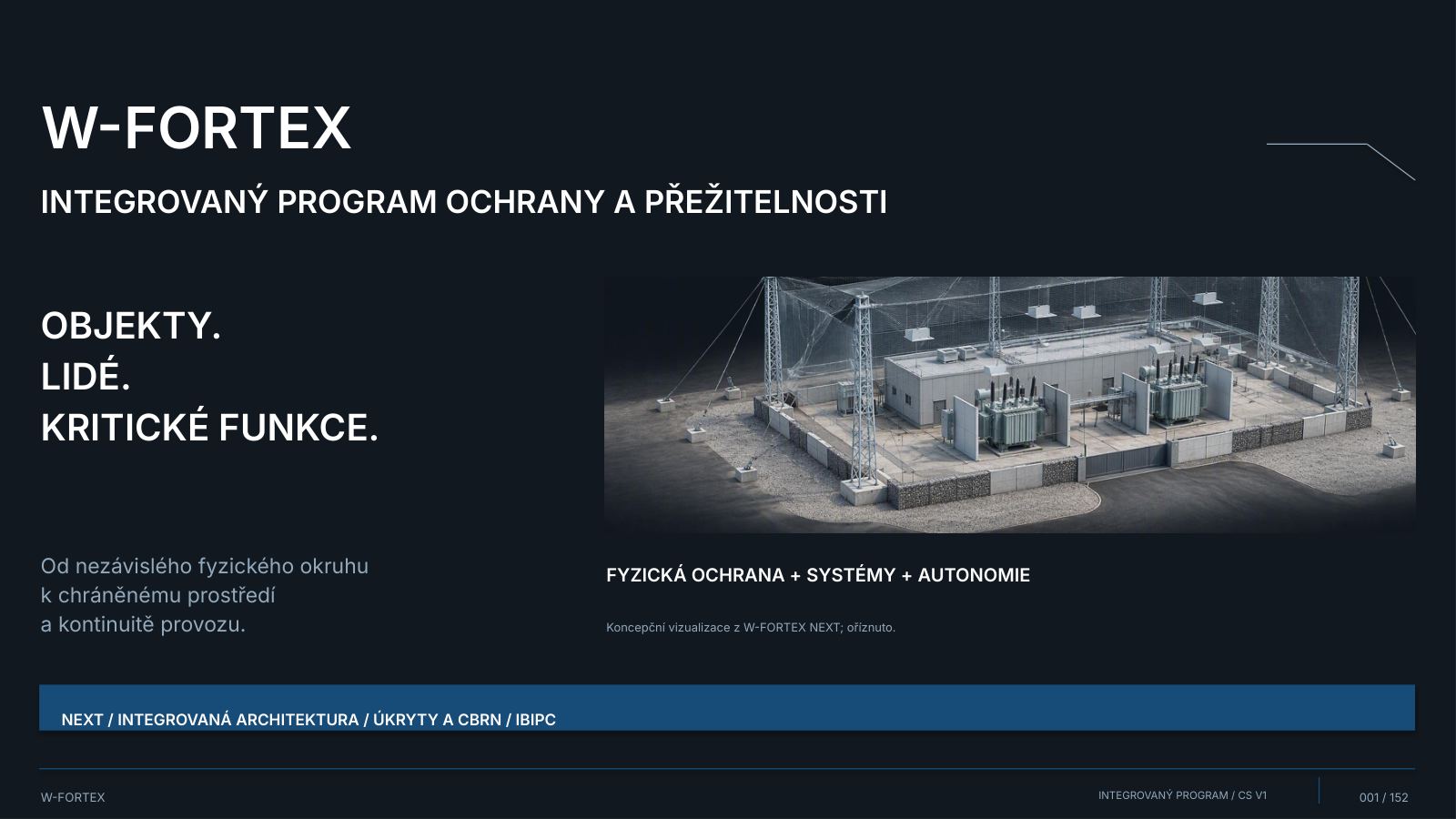
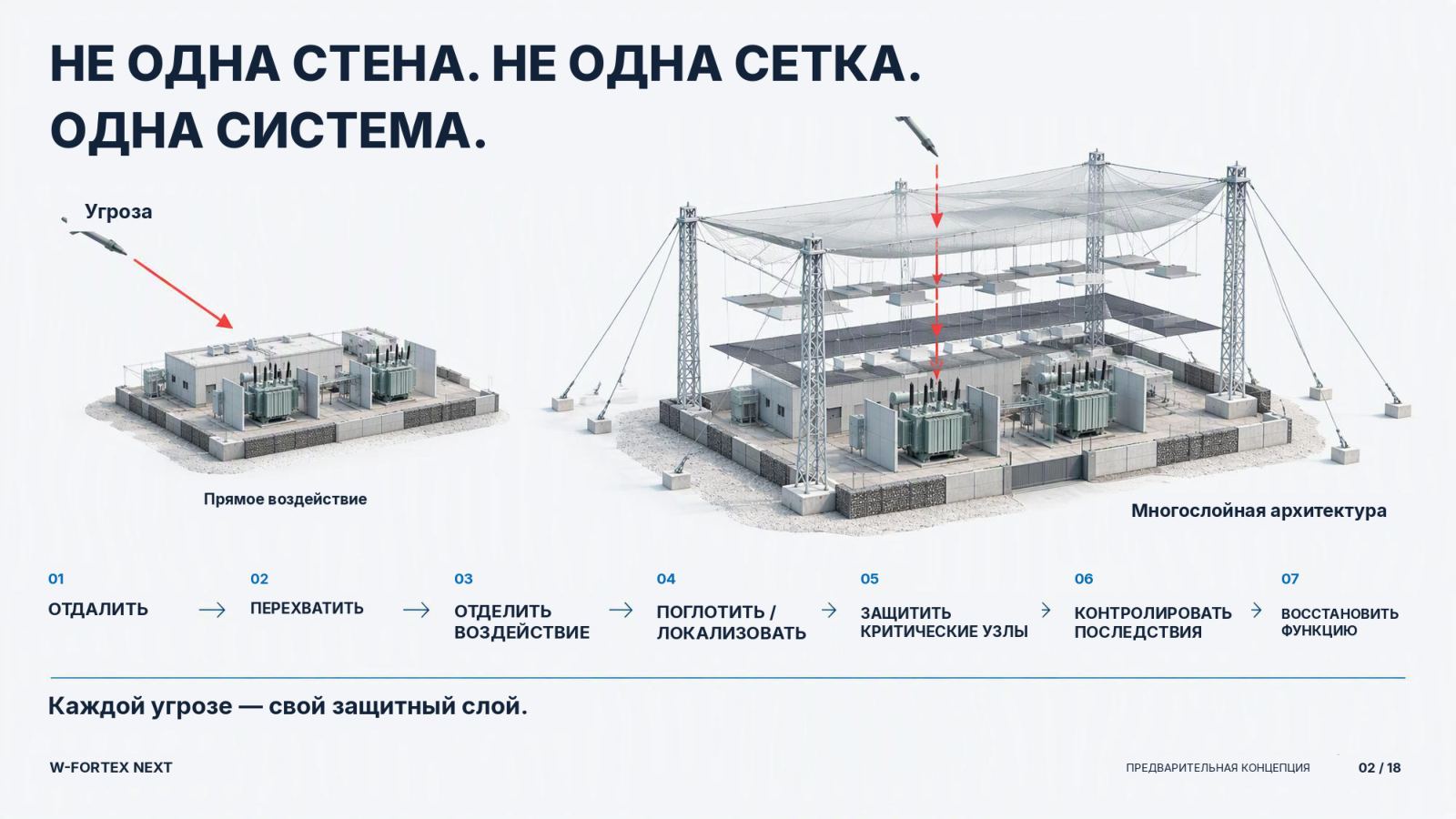
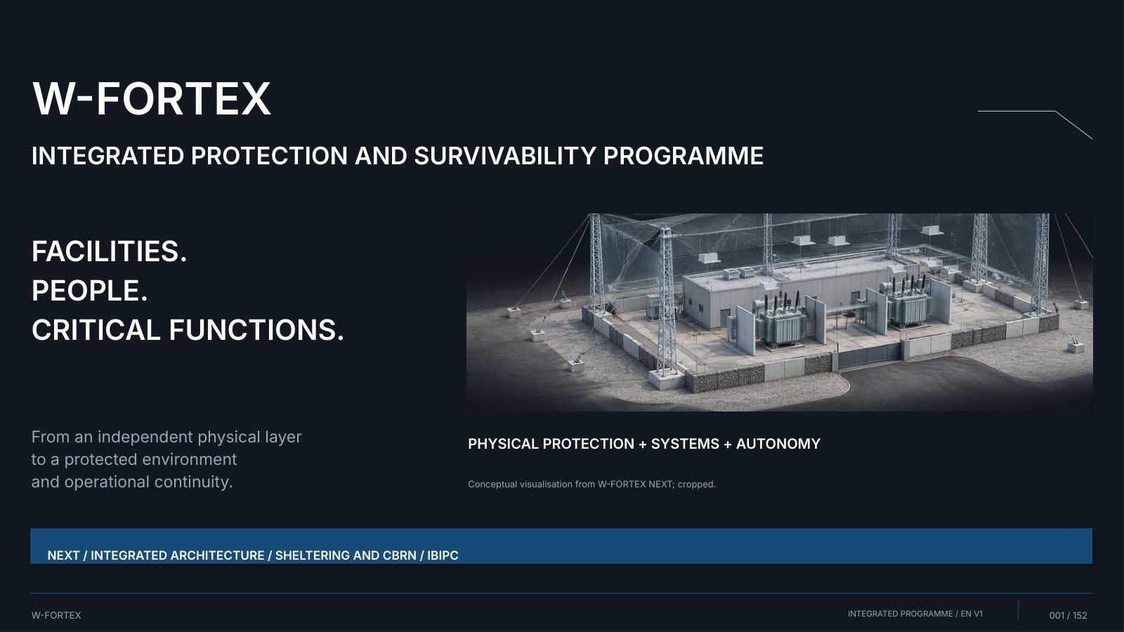
IW-FORTEX NEXT — Integrated Physical Protection and Survivability Platform
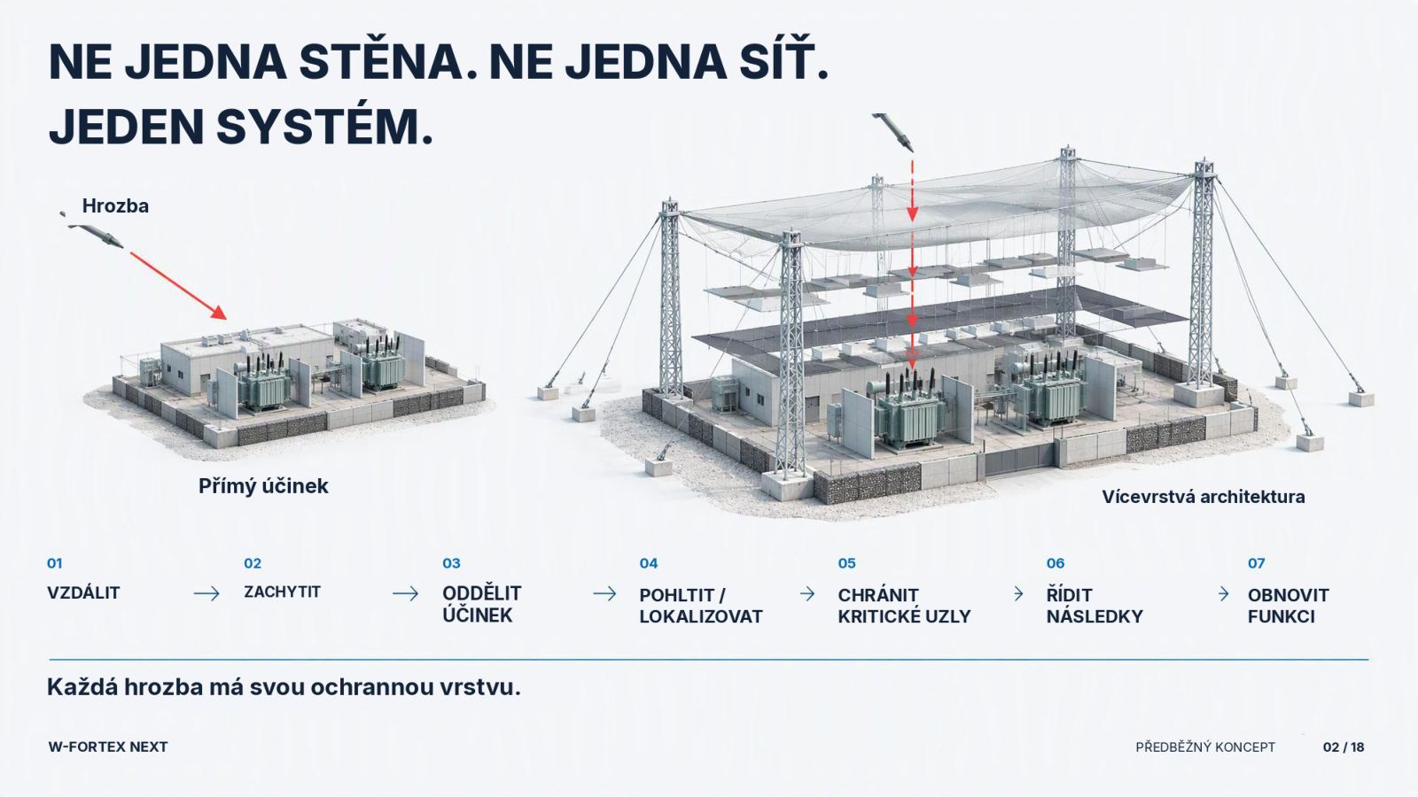
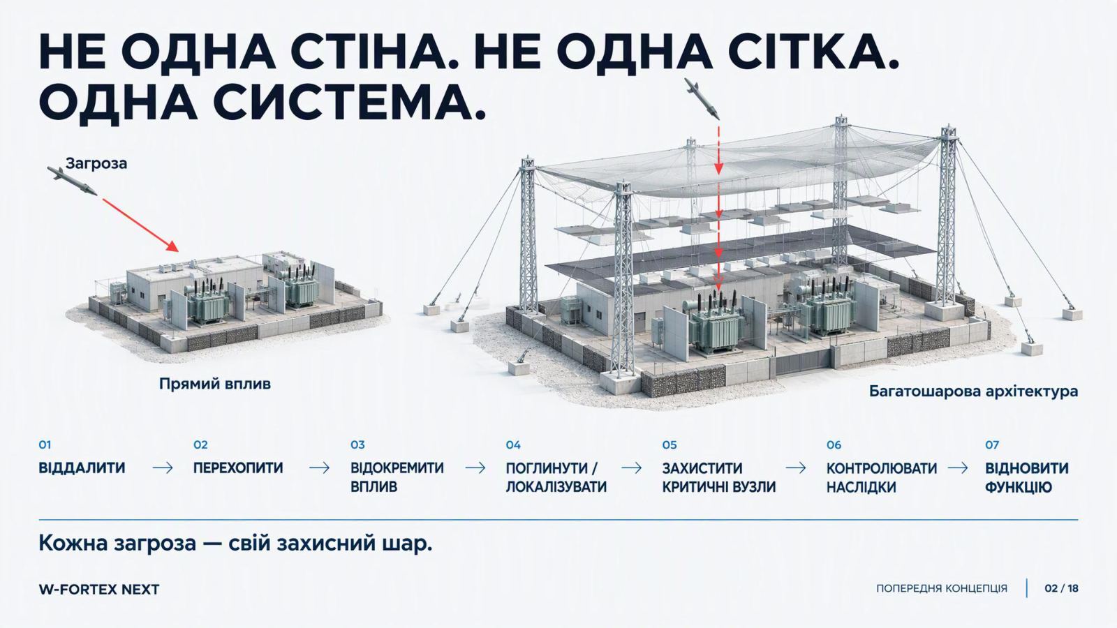
Not a single wall. Not a single net. One system. Each threat has its own protective layer. Critical infrastructure: energy · industry · transport · nuclear and radiological infrastructure.
- Perimeter — Independent supports; separation of impact
- Layers — Modularity; local protection
- Function — Consequences; recovery
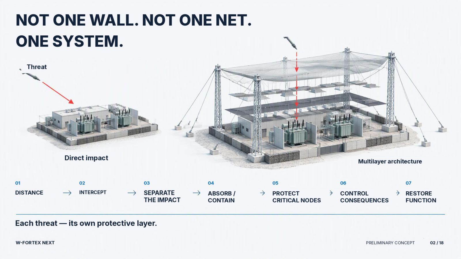
- Independent physical perimeter — protection is built around the facility, not at the facility’s expense
- Protection that does not rely on the facility — the primary load path leads to foundations and anchors
- Protective layers — deflect · intercept · isolate the impact · suppress/localise · protect critical nodes · control consequences · restore the function
- We protect the function — power supply, cooling, control, monitoring, emergency systems, access, containment, fire response, communications
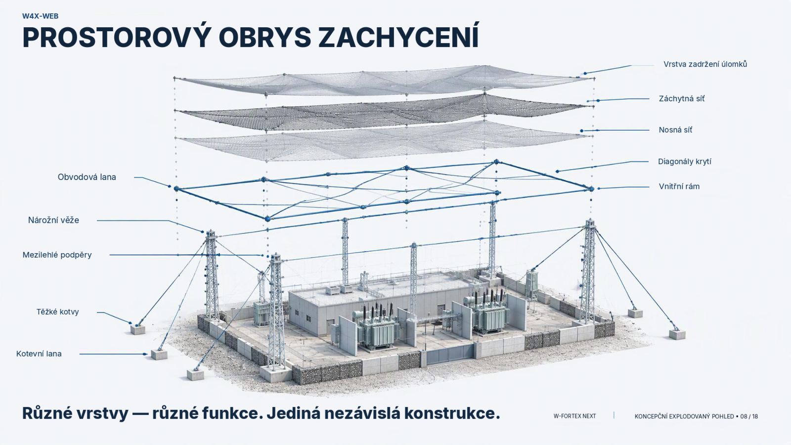
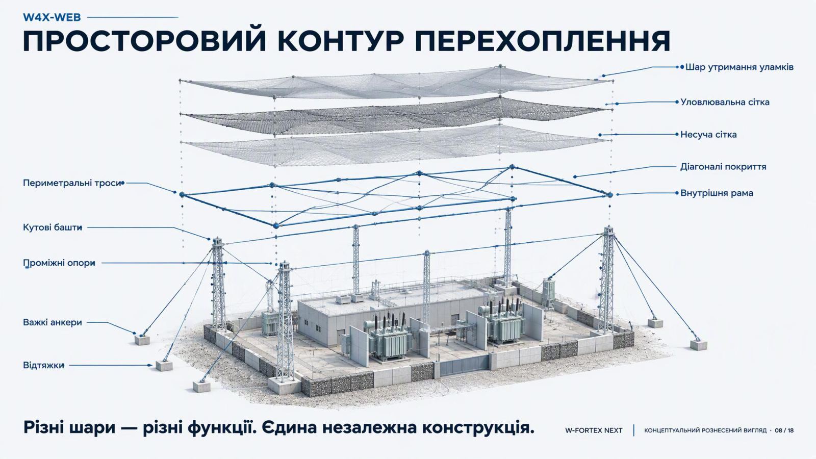
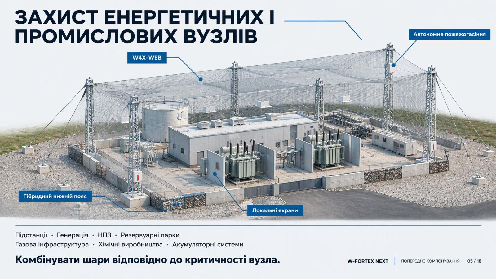
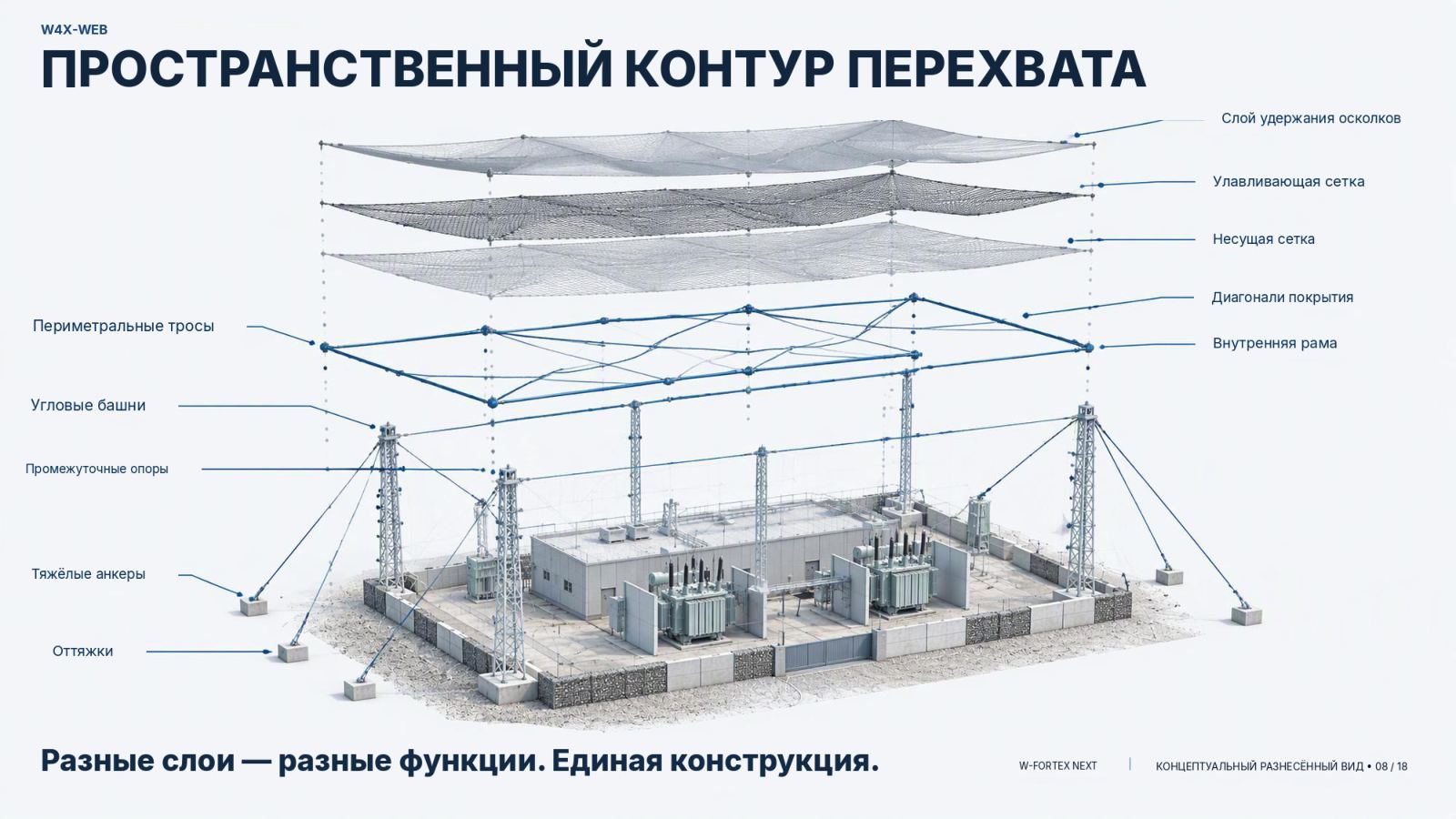
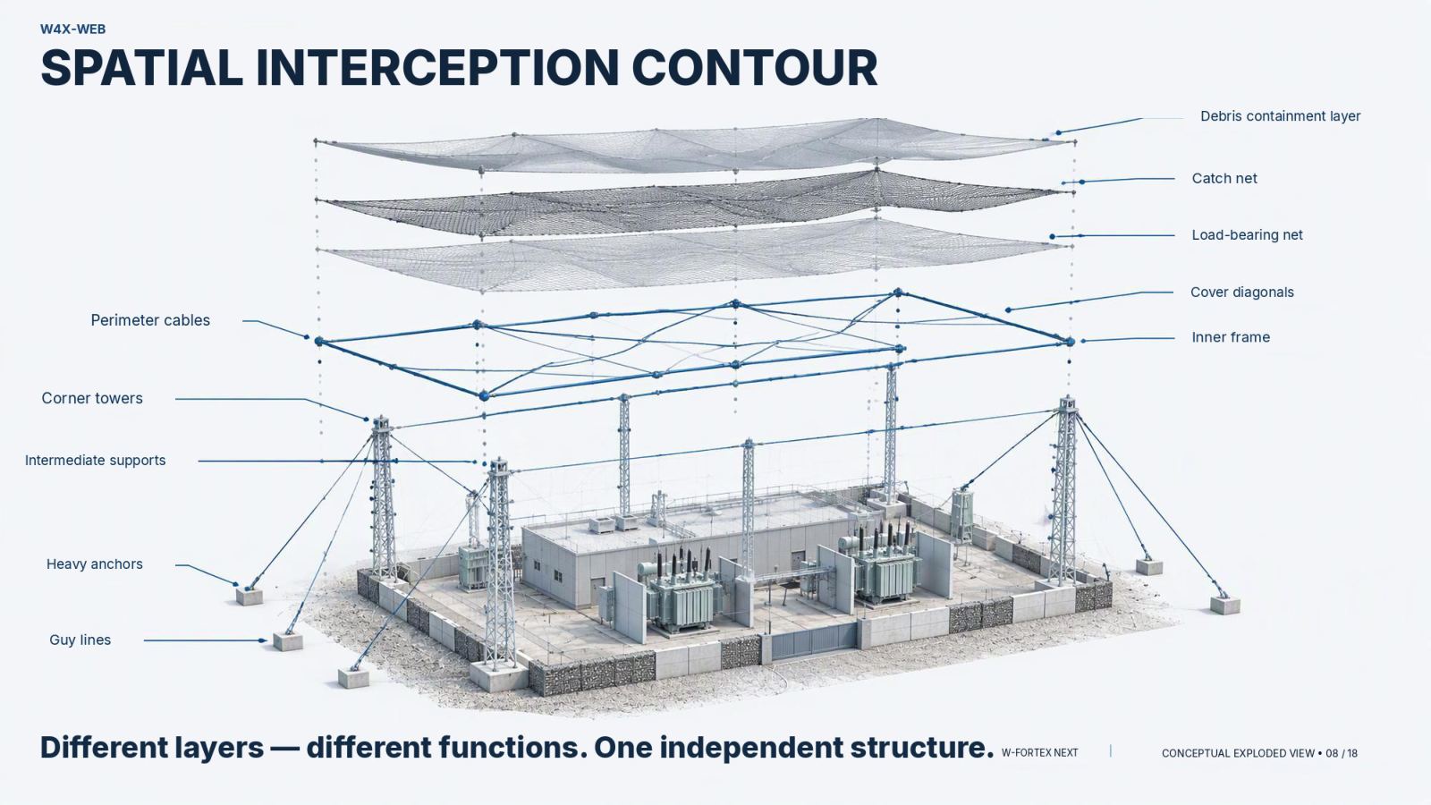
- W4X-WEB — a spatial interception perimeter
- Different layers — different functions — one independent structure
- Replaceability and repairability — damage the replaceable layer, preserve the critical facility
- Recovery sequence — inspect → isolate → replace → restore tension → return to service
- Reinforce where the value is greatest — a 1200×1200 mm suspended protective layer
- Alternative options — concrete slab, composite, UHPFRC, hybrid, NOVERA
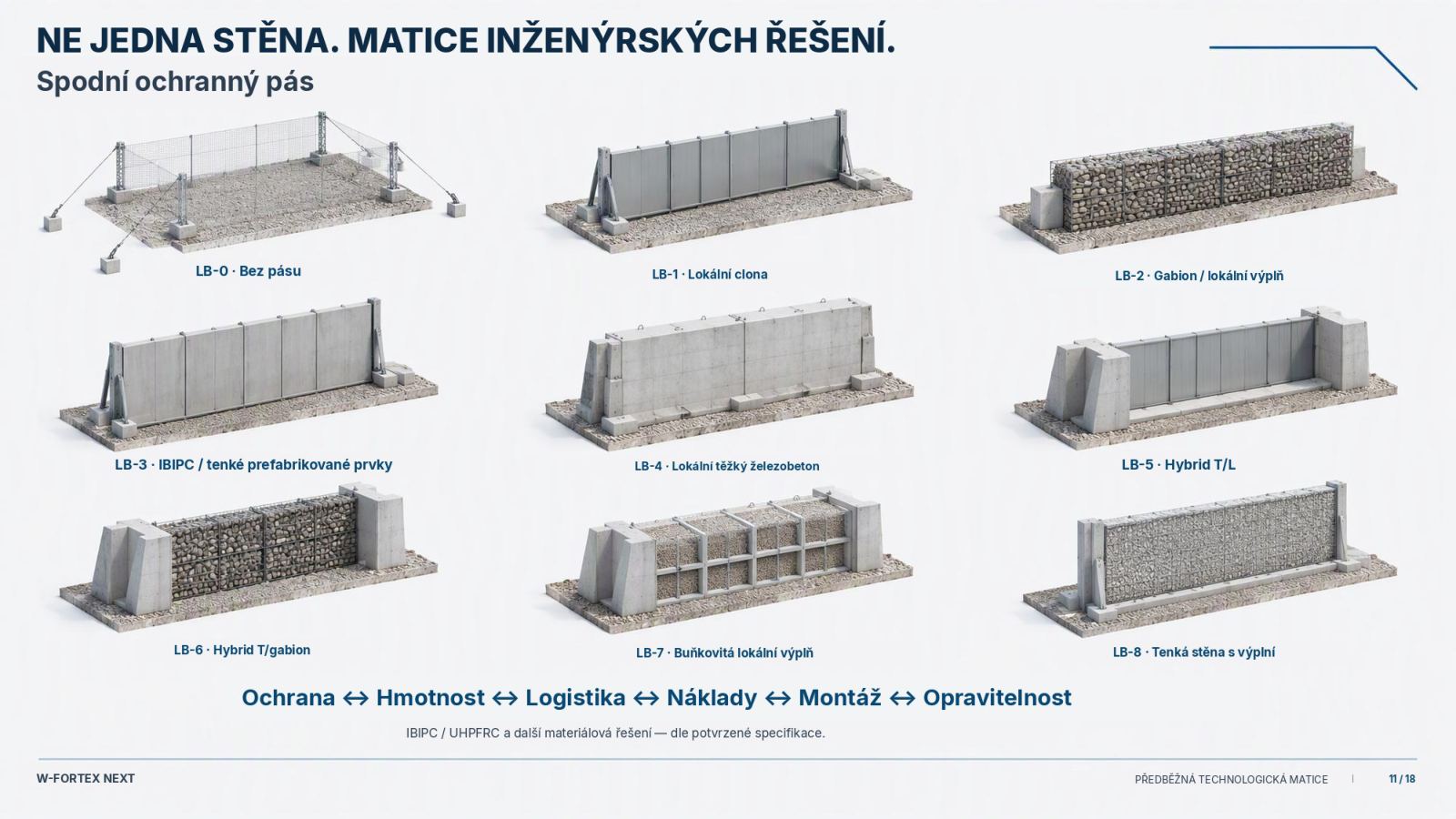
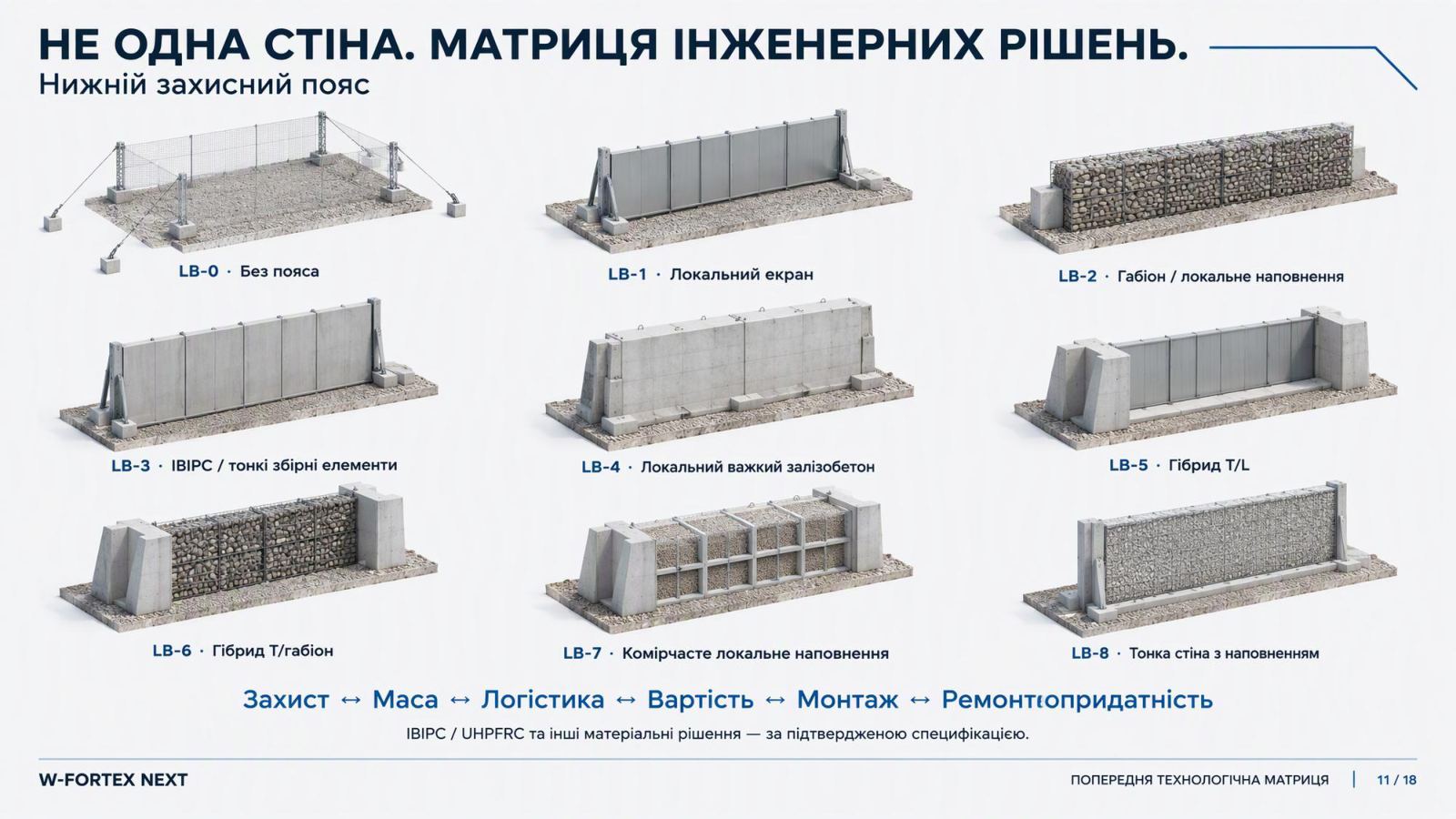
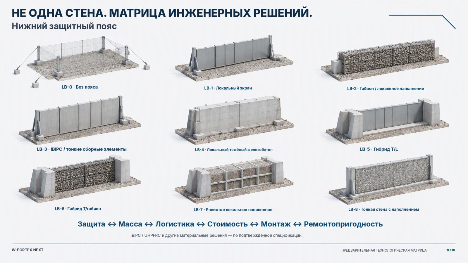
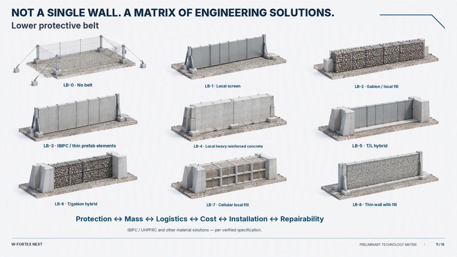
- Lower protective belt LB-0…LB-9 — no belt, local screen, gabion, IBIPC/UHPFRC, composite, T/L hybrid
- Not a single wall — a matrix of engineering solutions
- Critical nodes — priority protection: transformer, control, emergency power, process equipment
- Local reinforcement — IBIPC, UHPFRC, concrete wall, composite, local screens
- An impact is not the end of the scenario — 12 autonomous modules (3 per side)
- A complete response package — fire suppression, spill containment, drainage, local isolation, rapid repair
- Surface — a separate technological layer — NOVERA and the facility envelope: an additional independent protective perimeter
| Class | Description |
|---|---|
| C0 | WEB/WEB only |
| C1 | light |
| C2 | standard |
| C3 | enhanced |
| C4 | critical |
From geometry to preliminary economics: HEXA-CUBE / HCU is a preliminary commercial-configuration benchmark. W-FORTEX NEXT: protect the facility, isolate the impact, control the consequences, restore the function. Modularity. Independence. Adaptability. Survivability.
U01 FLEXFRAME — folding steel carrier for lower-belt infill
A universal carrier replacing the heavy precast T-element. Technical document Rev D, 20.10.2026 — a preliminarily approved concept for further development, not manufacturing documentation.
The W-FORTEX lower protective belt needs a stabilising "T" element. Precast T/L elements are heavy (≈ 6.5 t each), expensive to transport and require a heavy crane. U01 FLEXFRAME takes over this role with a steel frame: two vertical posts, braces and a base; the infill is lowered from above between the jaws.
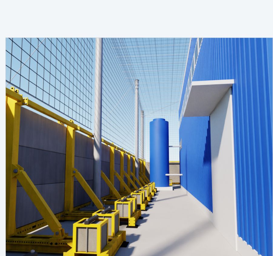
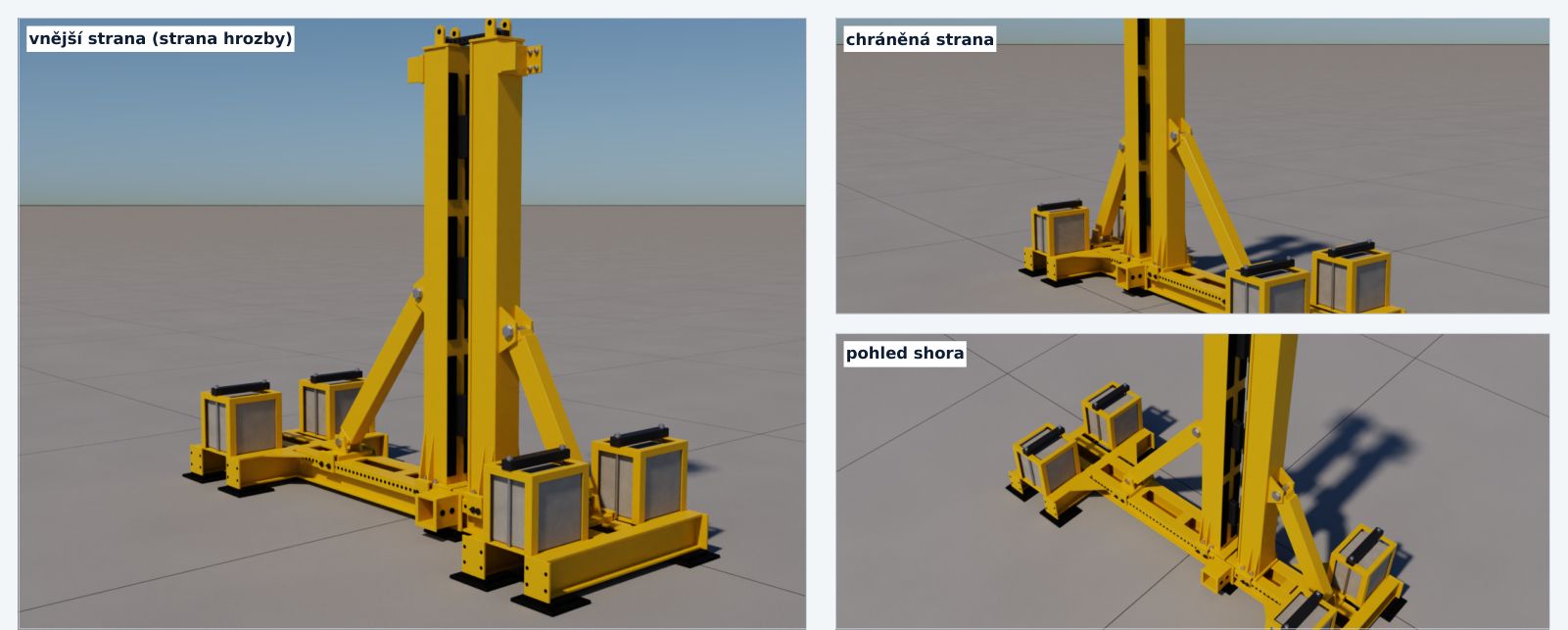
- Infill by threat and site — IBIPC 200 mm, local RC 300 mm (DBN) or a 500 mm gabion cassette
- No foundations — the belt stands on ballast or on anchors; only the upper-belt columns need foundations
- One post for 200–500 mm infill — the inner part slides on a carriage up to +300 mm in 50 mm steps
- Reusable — the post dismantles into flat parts with no oversize load; the infill is replaced without replacing steel
- In the configurator library — WF-LB-U01 (A anchored / B ballasted), WF-LB-U01-BP profile, WF-LB-U01-C corner column, WF-LB-U01-FC foundation column, assembly WF-LB-HU01
| # | Area | Rev D decision |
|---|---|---|
| D1 | Base mode | Common core + interchangeable rear module: B ballasted (no foundations) / A short anchored |
| D2 | Panel | 3000 × 1000 mm: IBIPC 200 (to be confirmed by the manufacturer) or local RC 300 |
| D3 | Height | 3 rows (top of panels +3.33 m) standard; 4 rows (+4.33 m) variant to be verified |
| D4 | Sections | Lightened: post 200×200×8, jaw 260×20, beams 240×100 — structural verification |
| D5 | Infill | 200–500 mm by shifting the inner part; wide U01-W (1000) separately |
| D6 | Corner | Separate corner column on a pile cap |
| D7 | Upper belt | Foundation columns (corners + intermediate) carry light masts; U01 without foundations |
| D8 | Joints | Bottom profile + upper rear clamp; continuous top beam as a variant |
| D9 | Corrosion protection | Pilot: three-coat paint; series: duplex (zinc + paint); pins always galvanised |
| D10 | Adjustment and transport | Index bars in 50 mm steps, pins, set screw; transport package T01 |
Three infill types in one frame
| IBIPC 200 | Local RC 300 (DBN) | Gabion cassette 500 | |
|---|---|---|---|
| Element size, mm | 3000 × 1000 × 200 | 3000 × 1000 × 300 | 3000 × 1000 × 500 |
| Element weight | ≈ 1,480 kg | ≈ 2,250 kg | ≈ 2,550 kg (filled) |
| Infill per 1 m of wall | ≈ 1.45 t | ≈ 2.2 t | ≈ 2.5 t (local) |
| Use | high threats, military sites | civil critical infrastructure | low-cost mass, less exposed sides |

Comparison with the precast L-30 element
| L-30 (RC) | U01 + RC 300 | U01 + IBIPC 200 | |
|---|---|---|---|
| Heaviest lift | ≈ 6.5 t | ≈ 2.3 t | ≈ 1.5 t |
| Concrete per 1 m | ≈ 3.3 t | ≈ 2.2 t | ≈ 1.45 t |
| Steel per 1 m | — | ≈ 0.68–0.84 t (reusable) | ≈ 0.68–0.84 t (reusable) |
| Wall thickness | 300 mm | 300 mm | 200 mm |
| Wall height | 3.65 m | 3.33 m | 3.33 m |
| Relocation / infill replacement | heavy crane / no | yes / yes | yes / yes |
| Link to upper belt | separate | via foundation columns | via foundation columns |
Reference offer: L-30 wall element, 2000 × 1000 × 3650 mm (DBN V.2.2-5:2023, 100 kPa). 100 kPa is a DBN blast-wave resistance class for protective structures, not a ballistic or anti-fragmentation class; it cannot be compared directly with STANAG.
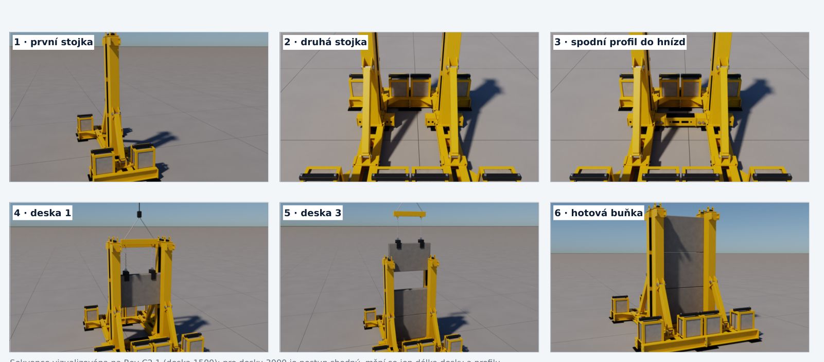
Next steps: structural analysis of the post and steel optimisation (target ≤ 600 kg/m), confirmation of the IBIPC 3000 × 1000 × 200 panel, local RC panel to DBN, cell prototype (2 × U01 + 3 infills) and tests, WF-LB-U01-* library cards and GLB models for the configurator.
Rev D is a preliminarily approved concept for further development. It does not claim load-bearing capacity, ballistic or blast resistance and does not replace manufacturing documentation or tests.
Download the U01 FLEXFRAME Rev D technical document (PDF, CZ) ↓
One Platform — Different Industries
Energy, industry, oil and gas, transport, civil critical infrastructure, nuclear facilities, radiological facilities. The architecture adapts to the function and geometry of the facility.
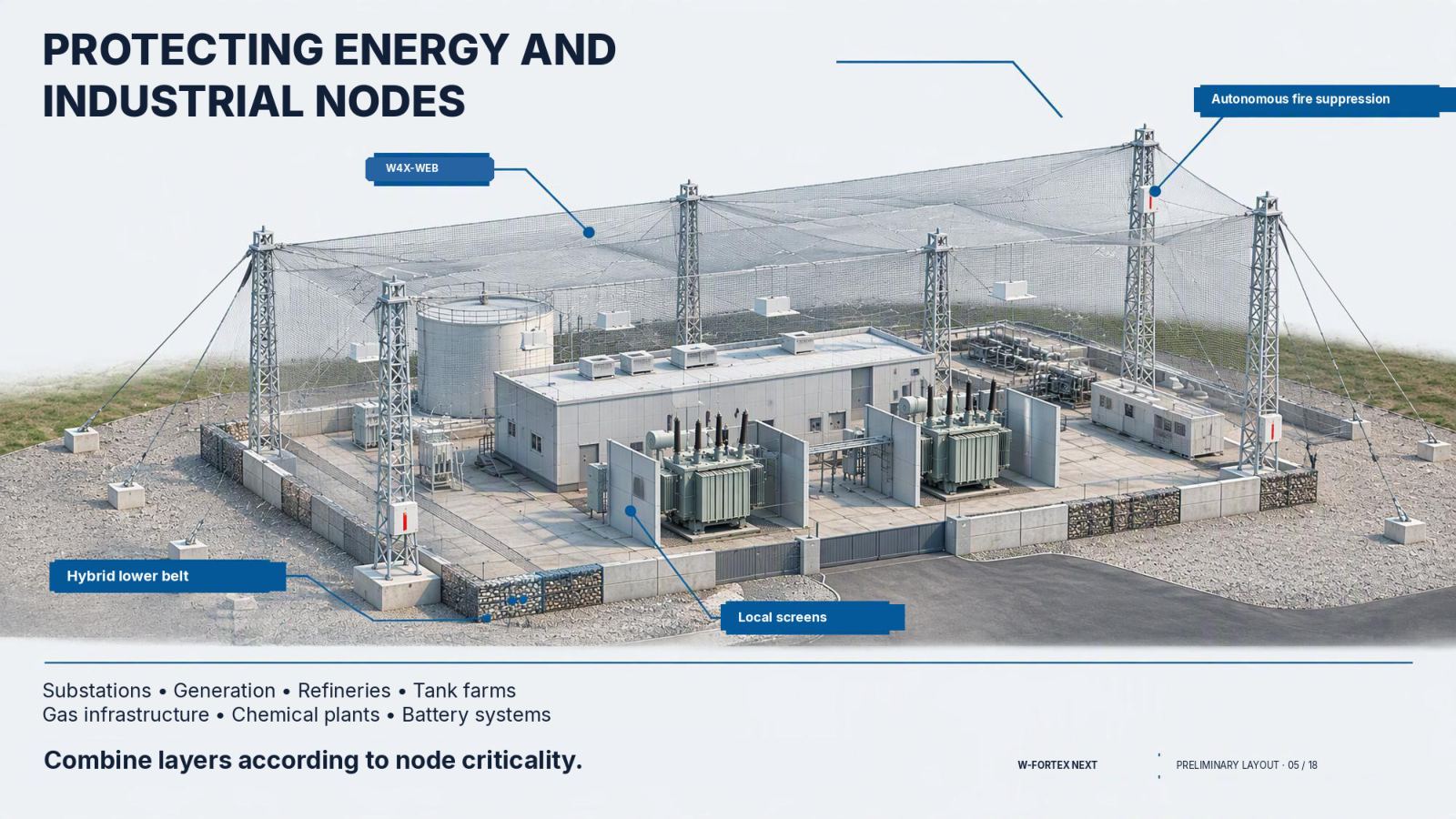
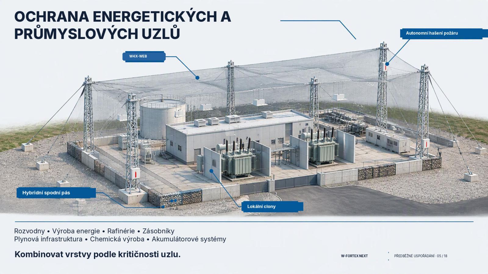
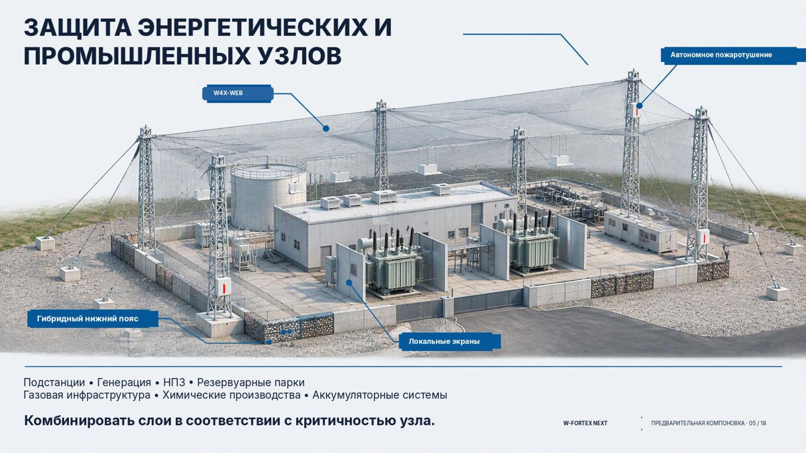
- Substations, generation — combine layers according to the criticality of the node
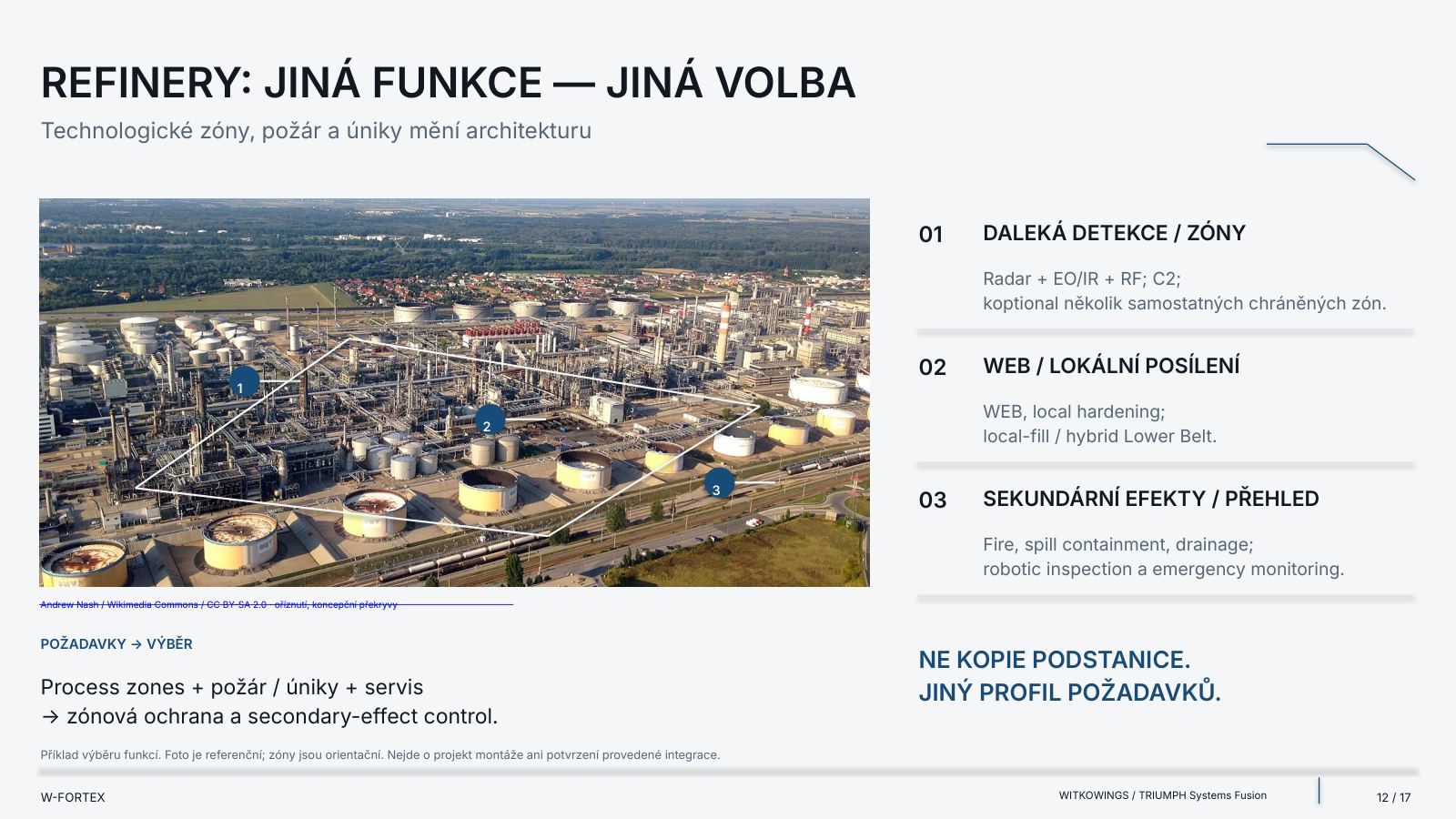
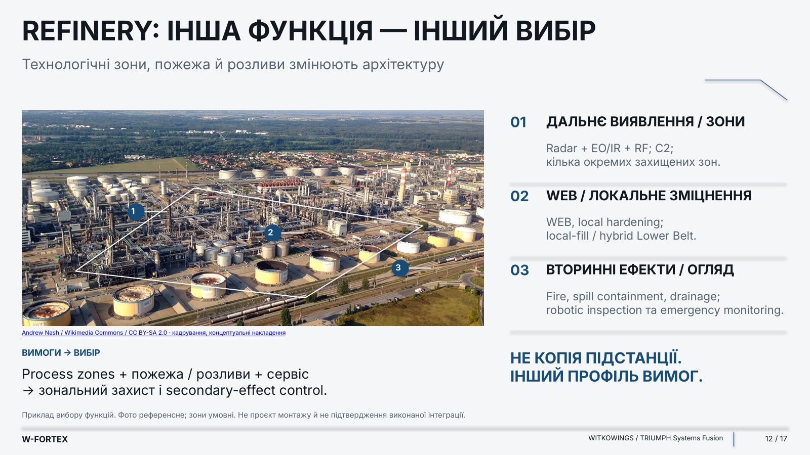
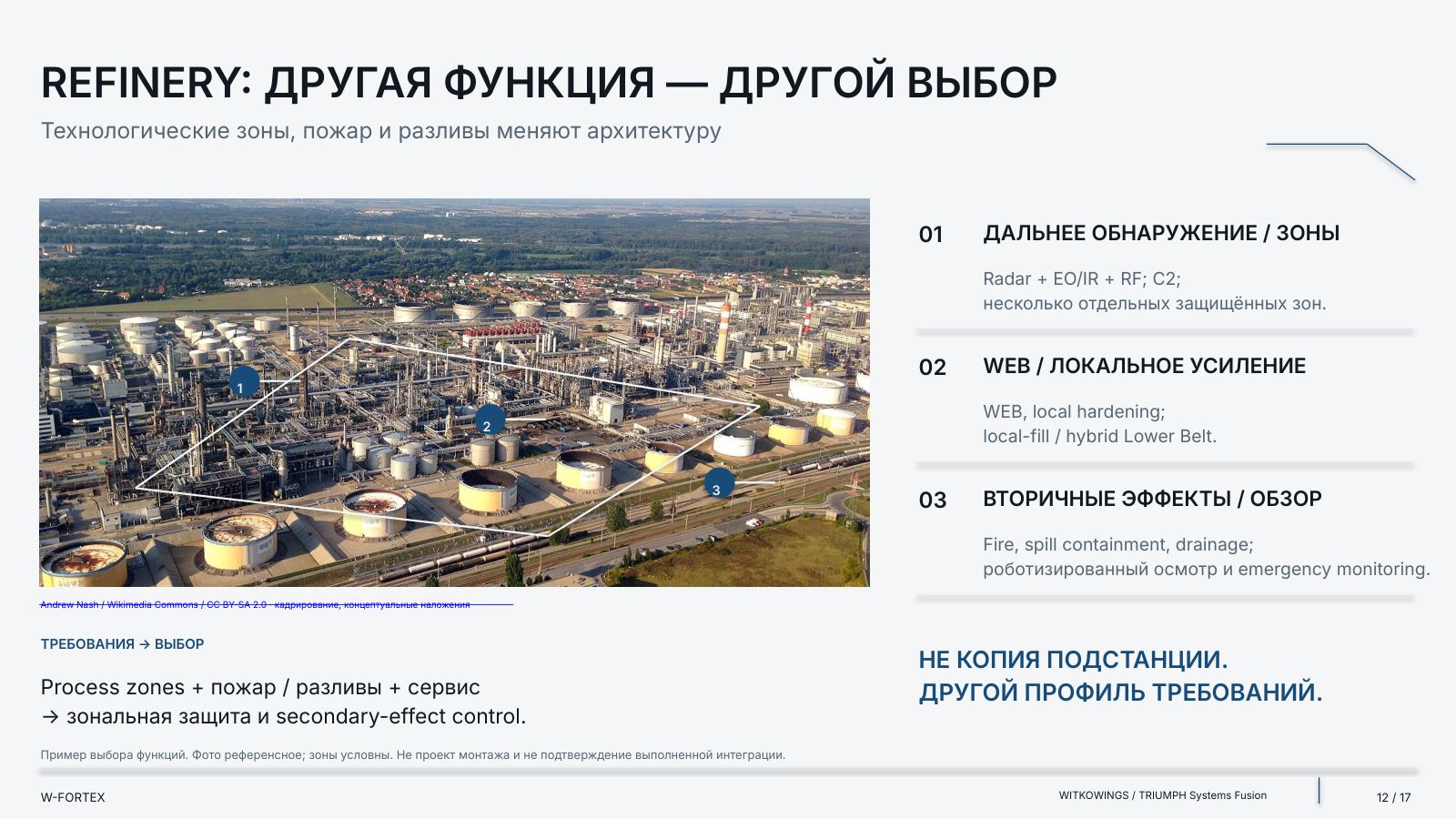
- Refineries, tank farms — process zones, fire and spills change the architecture
- Gas infrastructure, chemical production — nodes of differing criticality require different layer combinations
- Battery systems — also among the nodes for which protective layers are combined
| Industry | 01 | 02 | 03 |
|---|---|---|---|
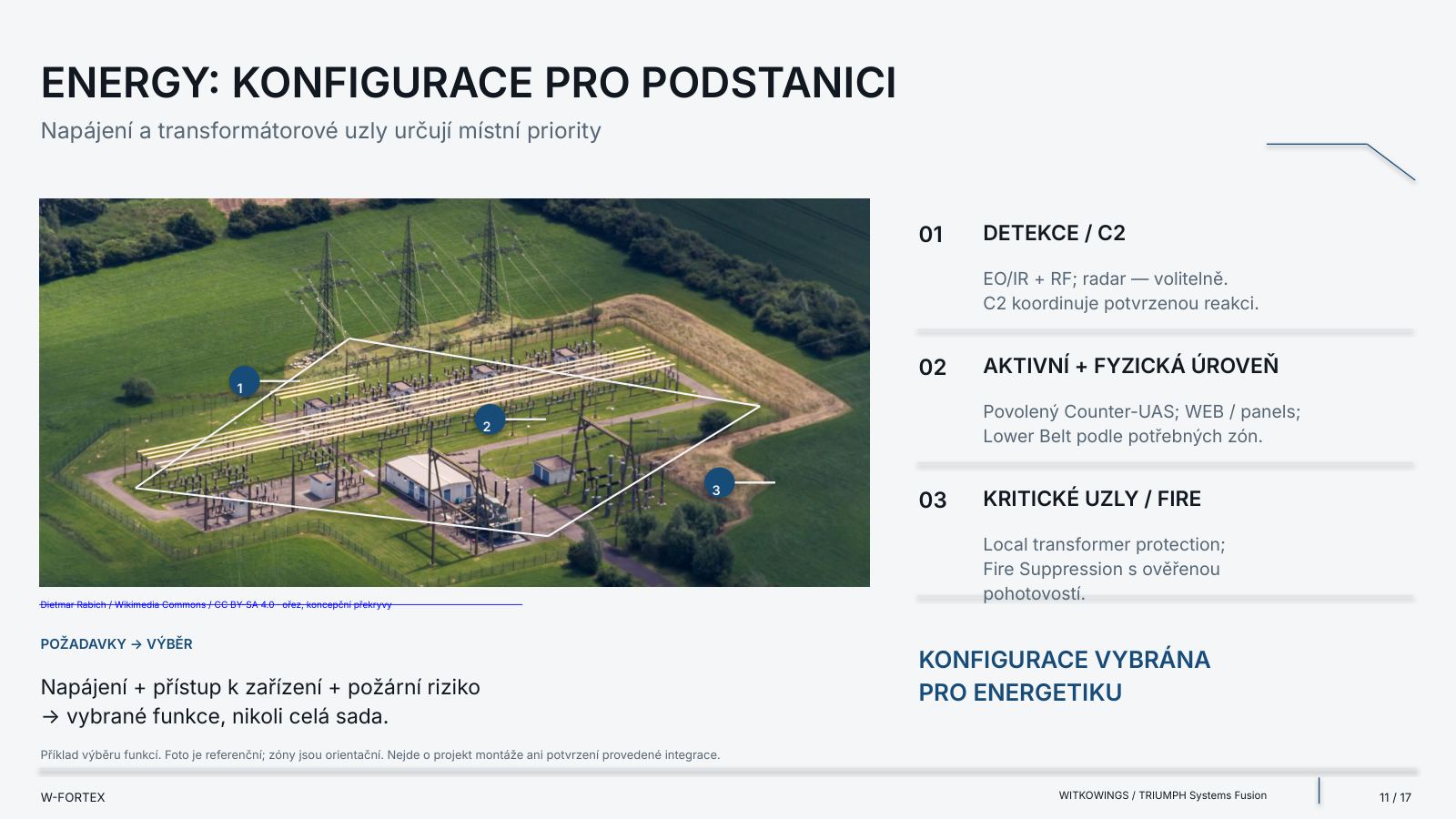
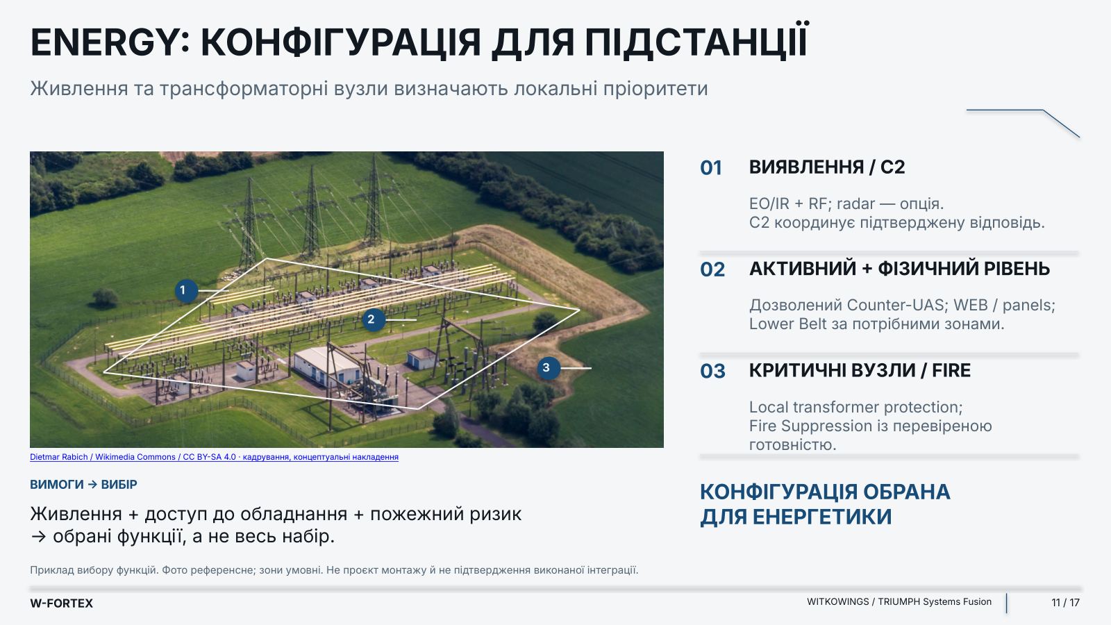
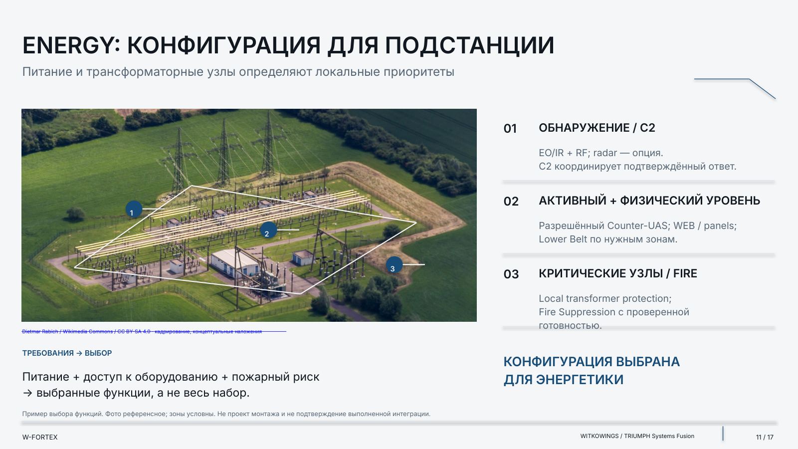
| Energy | Detection / C2: EO/IR + RF; radar — optional. C2 coordinates a confirmed response. | Active + physical layer: authorised Counter-UAS; WEB / panels; Lower Belt for the required zones. | Critical nodes / Fire: local transformer protection; Fire Suppression with verified readiness. |
| Refinery | Long-range detection / zones: Radar + EO/IR + RF; C2; several separate protected zones. | WEB / local hardening: WEB, local hardening; local-fill / hybrid Lower Belt. | Secondary effects / inspection: Fire, spill containment, drainage; robotic inspection and emergency monitoring. |
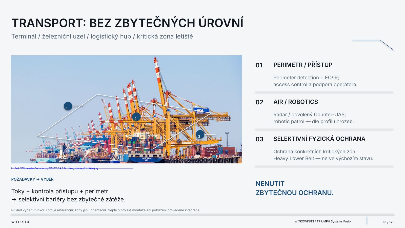
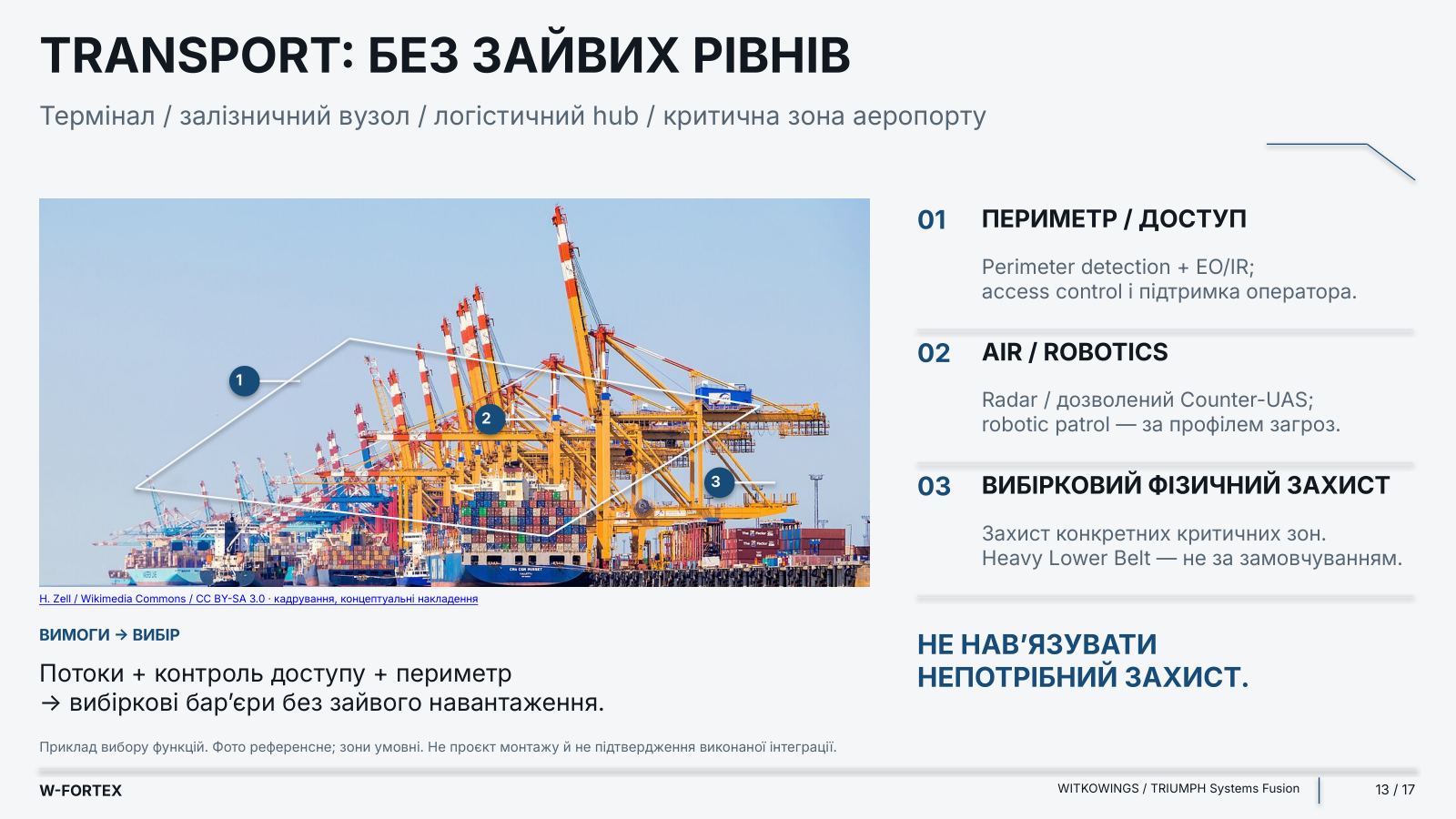
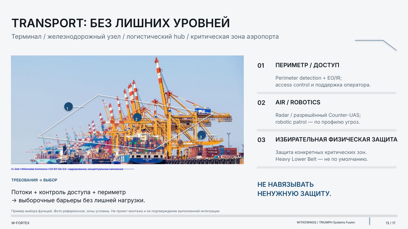
| Transport | Perimeter / access: Perimeter detection + EO/IR; access control and operator support. | Air / Robotics: Radar / authorised Counter-UAS; robotic patrol — according to the threat profile. | Selective physical protection: protection of specific critical zones. Heavy Lower Belt — not the default. |
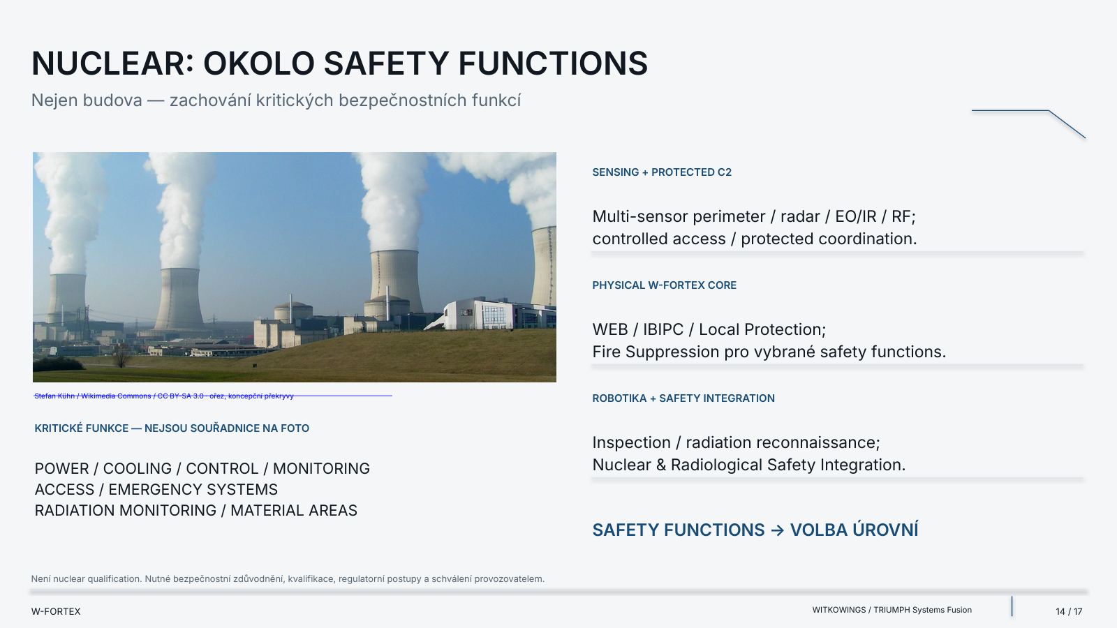
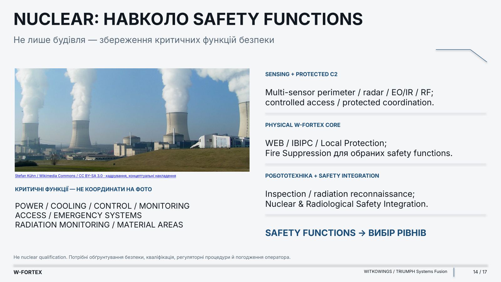
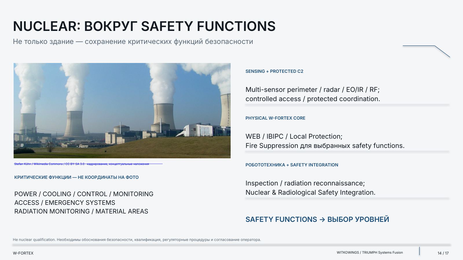
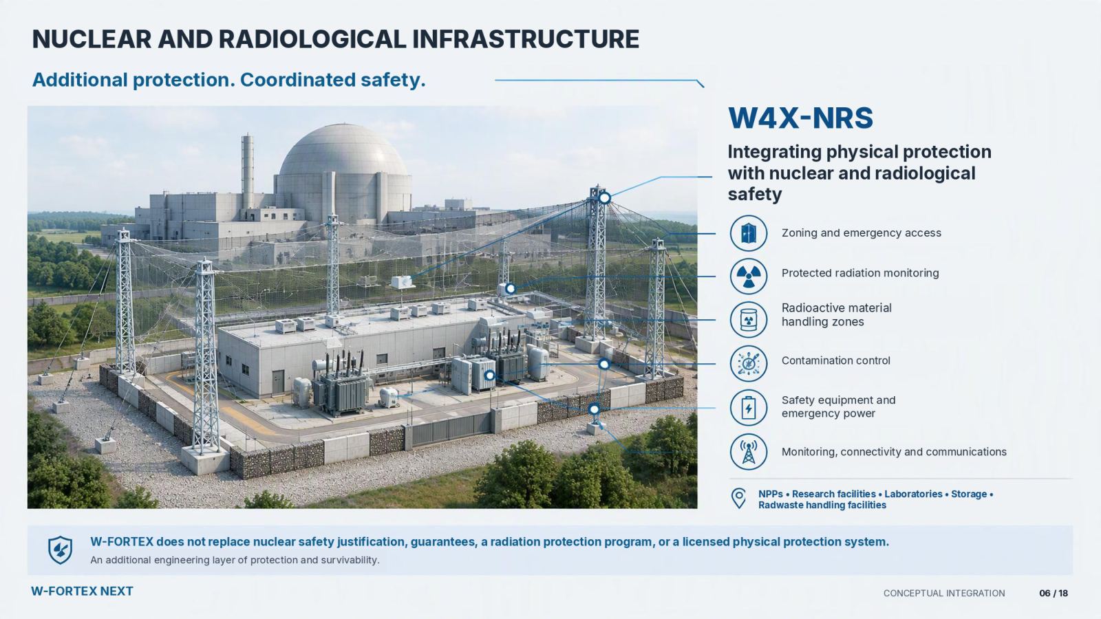
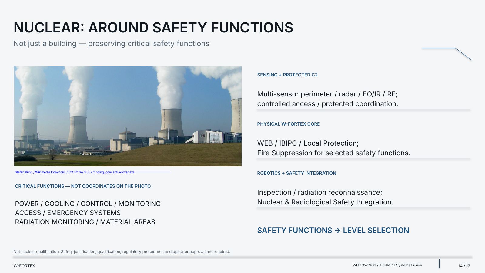
| Nuclear / radiological | Sensing + protected C2: Multi-sensor perimeter / radar / EO/IR / RF; controlled access / protected coordination. | Physical W-FORTEX core: WEB / IBIPC / Local Protection; Fire Suppression for selected safety functions. | Robotics + safety integration: Inspection / radiation reconnaissance; Nuclear & Radiological Safety Integration. |
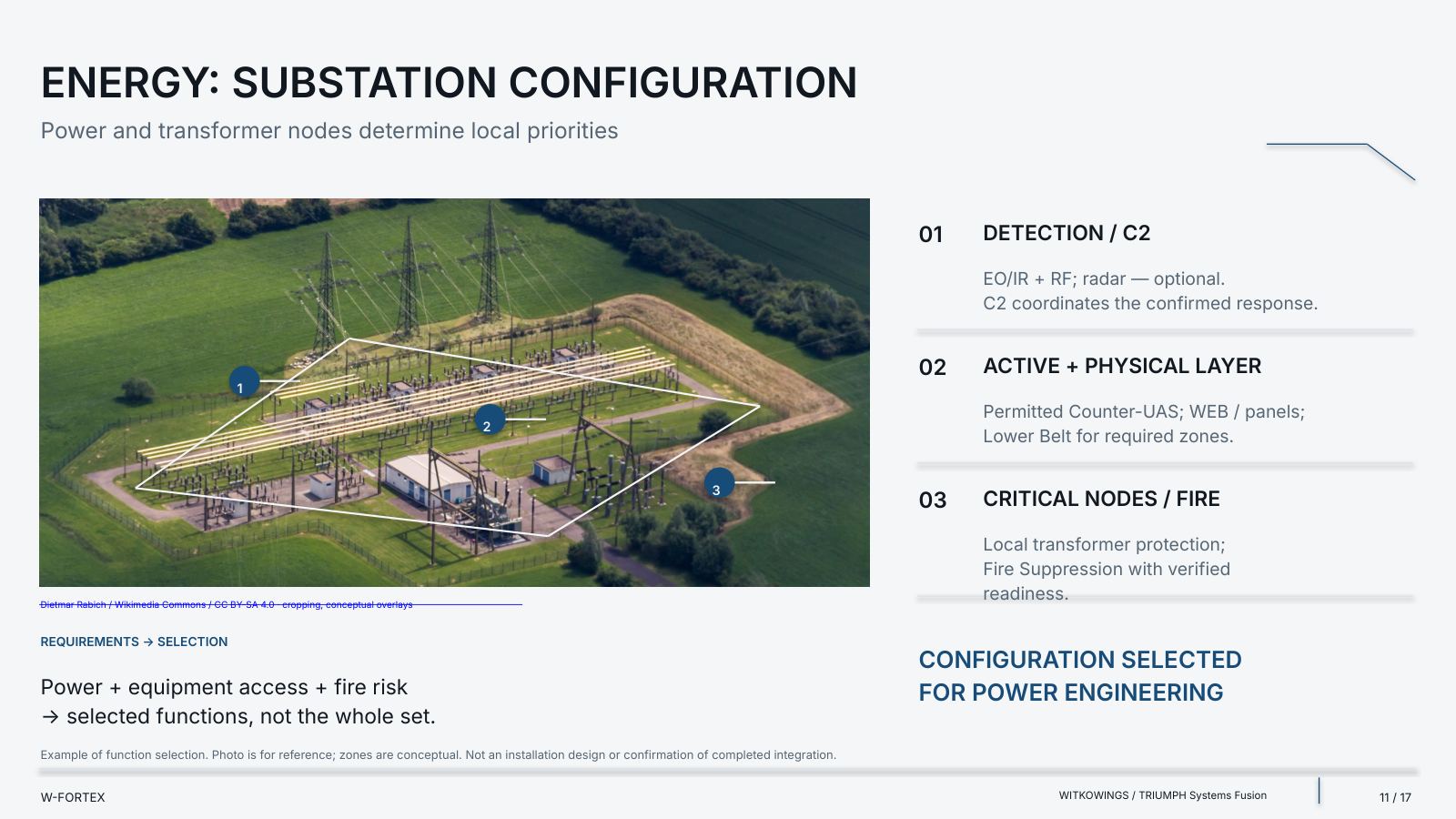
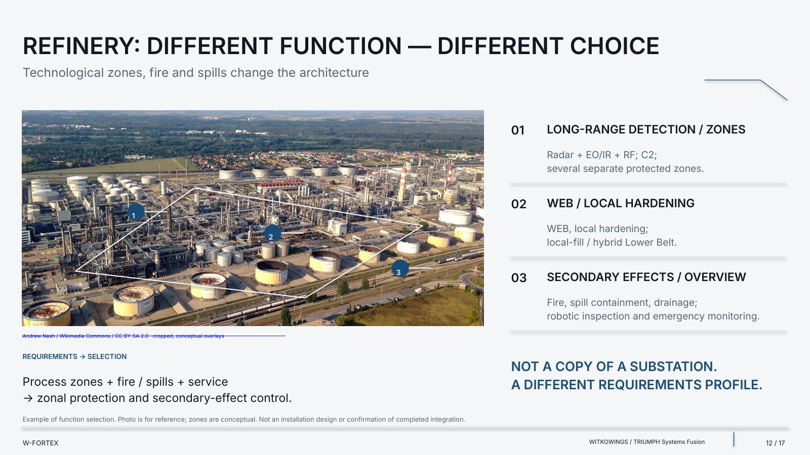
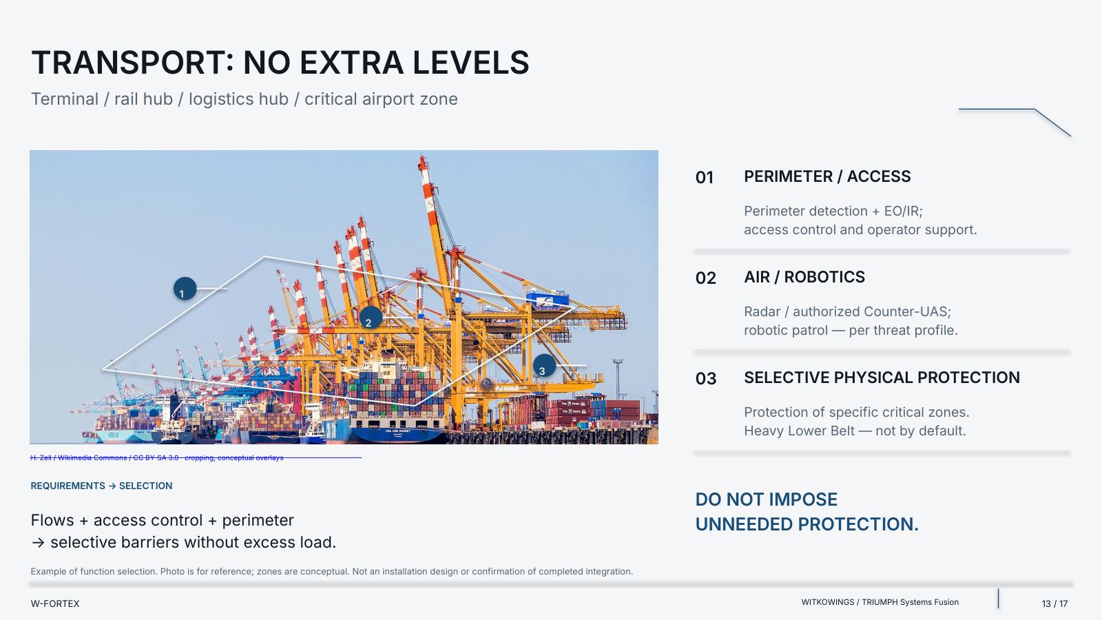
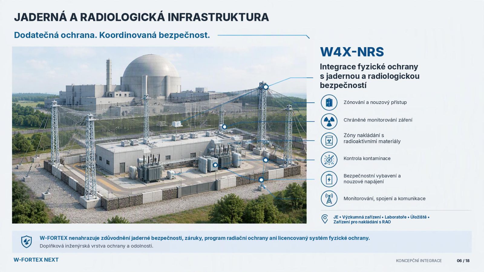
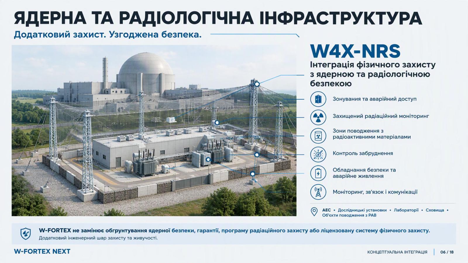
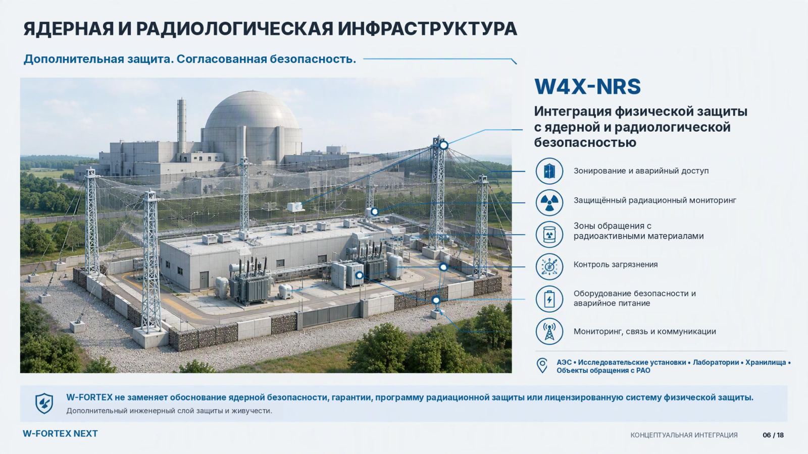
- W4X-NRS — integration of physical protection with nuclear and radiological safety
- Critical functions — not coordinates on a photo: power / cooling / control / monitoring; access / emergency systems; radiation monitoring / material areas
- Limit — W-FORTEX does not change the nuclear safety justification
- Not nuclear qualification — safety justifications, qualification, regulatory procedures and operator approval are required
IIIntegrated Protection Architecture
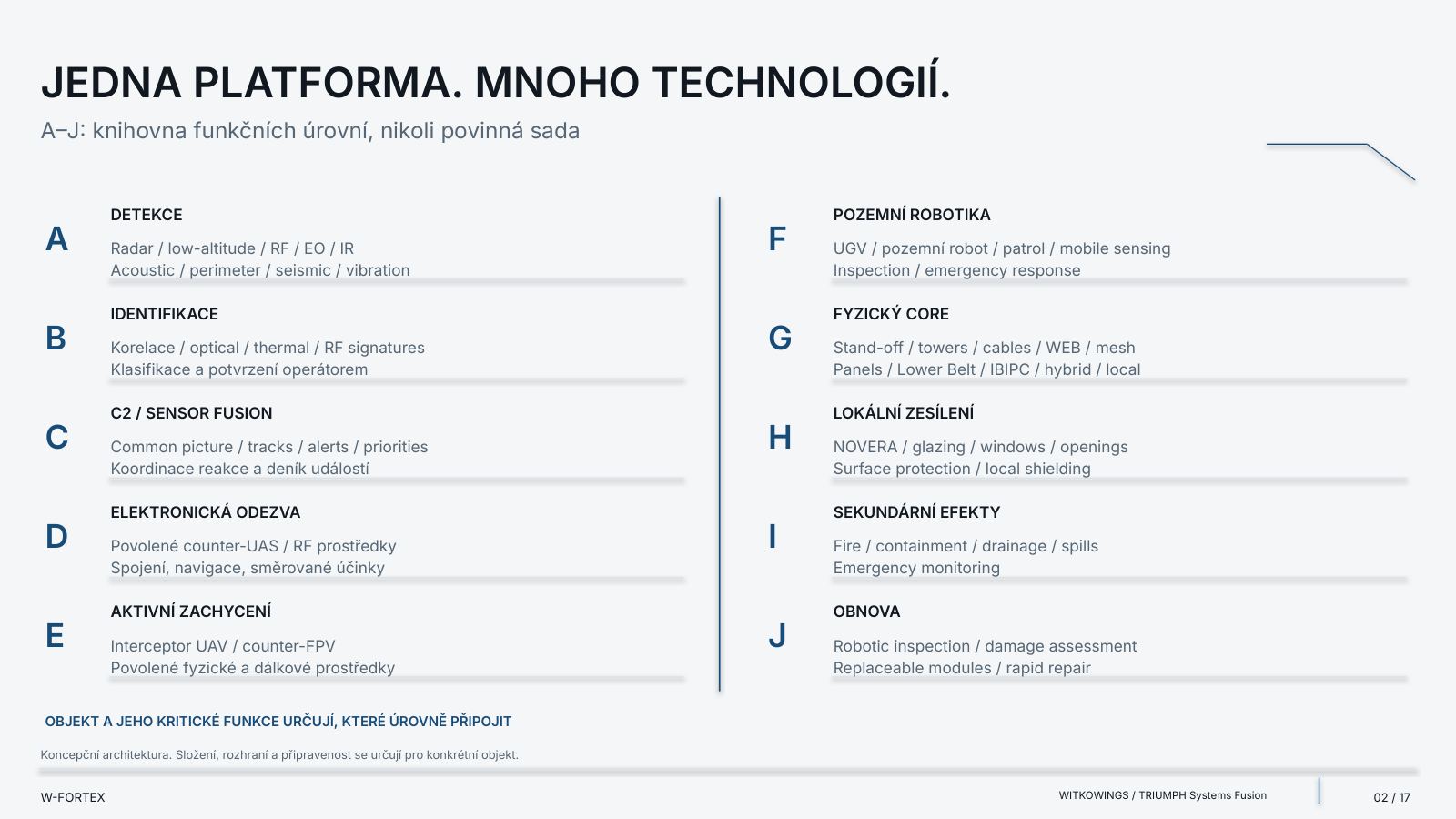
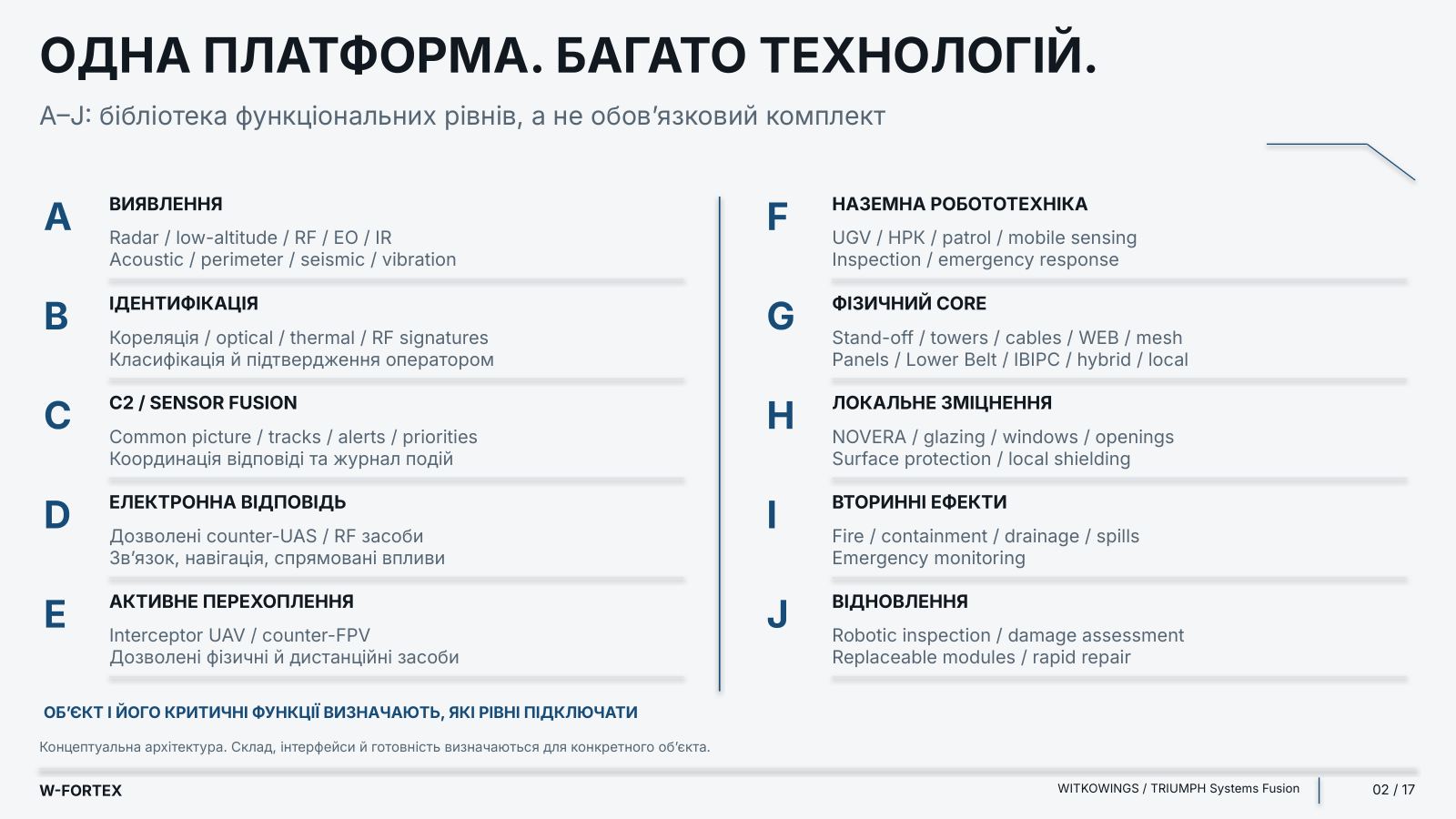
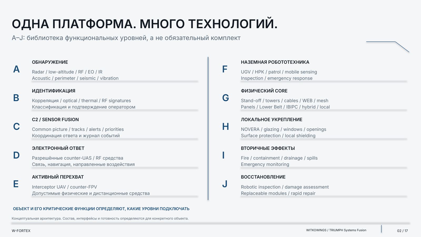
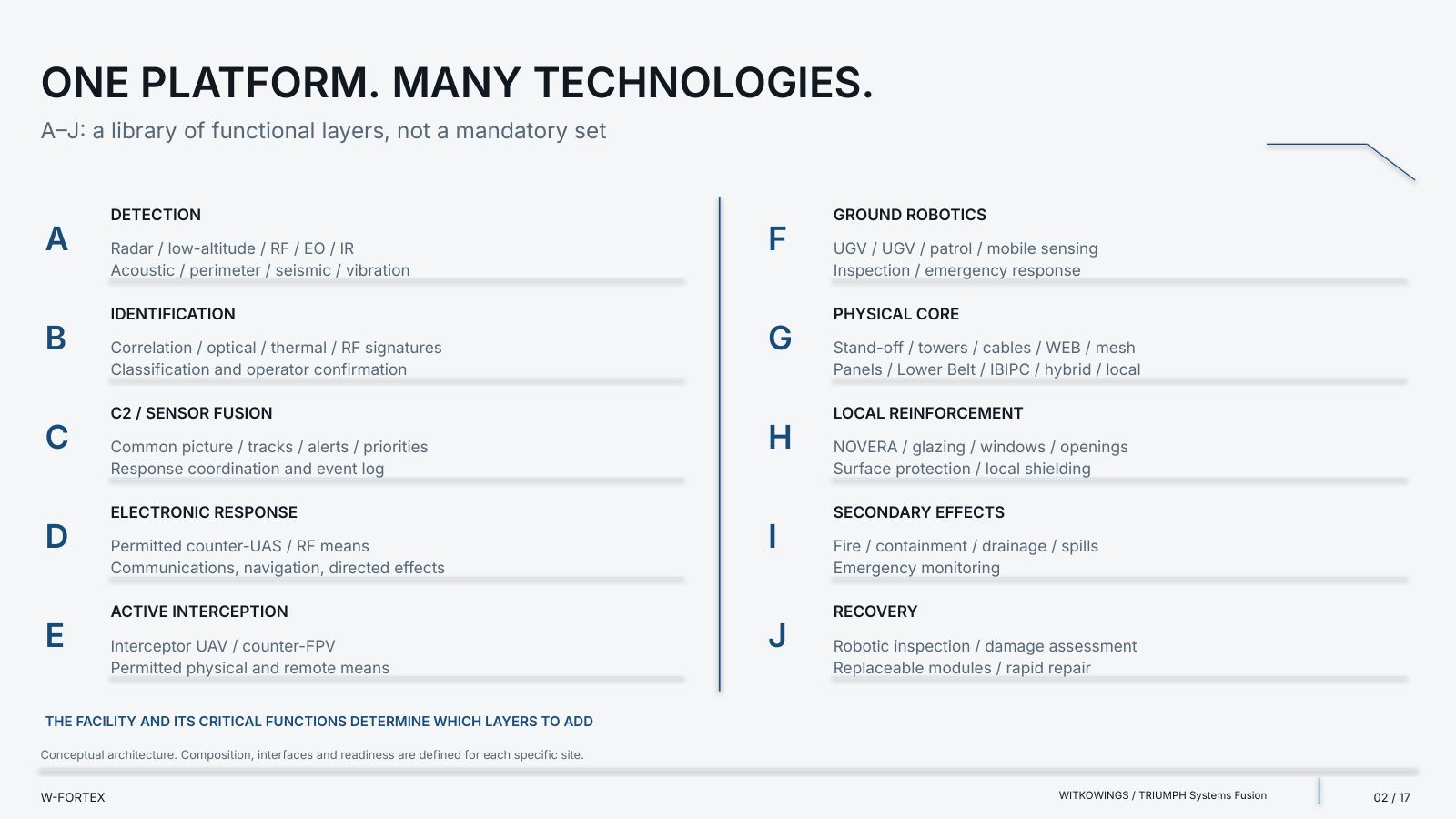
A modular concept for critical infrastructure. From function selection to qualified integration. One platform. Many technologies. Its own configuration: physical core + active layers + robotic recovery. The physical core is supplemented with exactly those functions that a specific facility needs.
| Layer | Title | Examples |
|---|---|---|
| A | DETECTION | Radar / low-altitude / RF / EO / IR; Acoustic / perimeter / seismic / vibration |
| B | IDENTIFICATION | Correlation / optical / thermal / RF signatures; Classification and operator confirmation |
| C | C2 / SENSOR FUSION | Common picture / tracks / alerts / priorities; Response coordination and event log |
| D | ELECTRONIC RESPONSE | Authorised counter-UAS / RF means; Communications, navigation, directed effects |
| E | ACTIVE INTERCEPTION | Interceptor UAV / counter-FPV; Authorised physical and remote means |
| F | GROUND ROBOTICS | UGV / GRS / patrol / mobile sensing; Inspection / emergency response |
| G | PHYSICAL CORE | Stand-off / towers / cables / WEB / mesh; Panels / Lower Belt / IBIPC / hybrid / local |
| H | LOCAL HARDENING | NOVERA / glazing / windows / openings; Surface protection / local shielding |
| I | SECONDARY EFFECTS | Fire / containment / drainage / spills; Emergency monitoring |
| J | RECOVERY | Robotic inspection / damage assessment; Replaceable modules / rapid repair |
A–J: a library of functional layers, not a mandatory kit. Conceptual architecture. The composition, interfaces and readiness are defined for each specific facility. The facility and its critical functions determine which layers to connect.
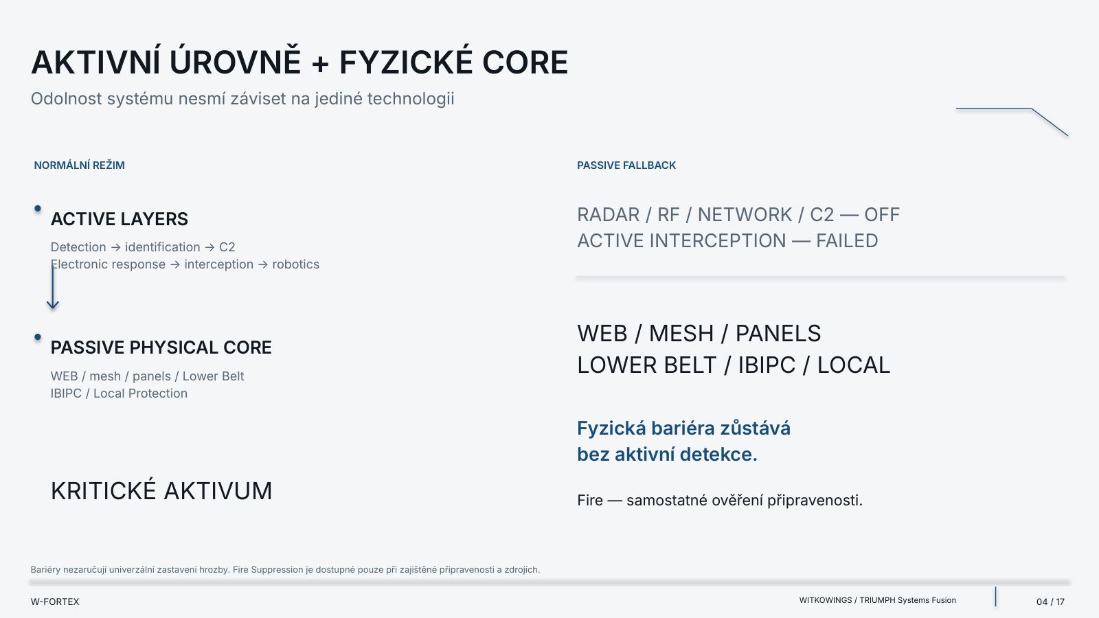
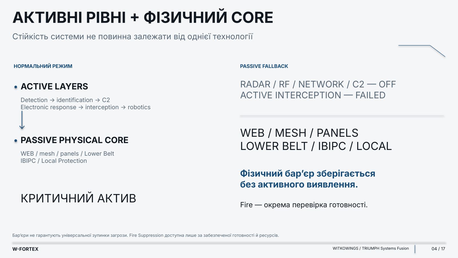
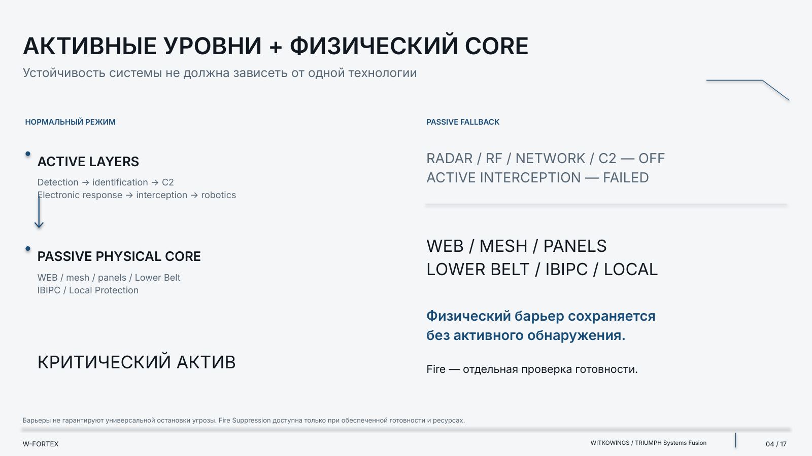
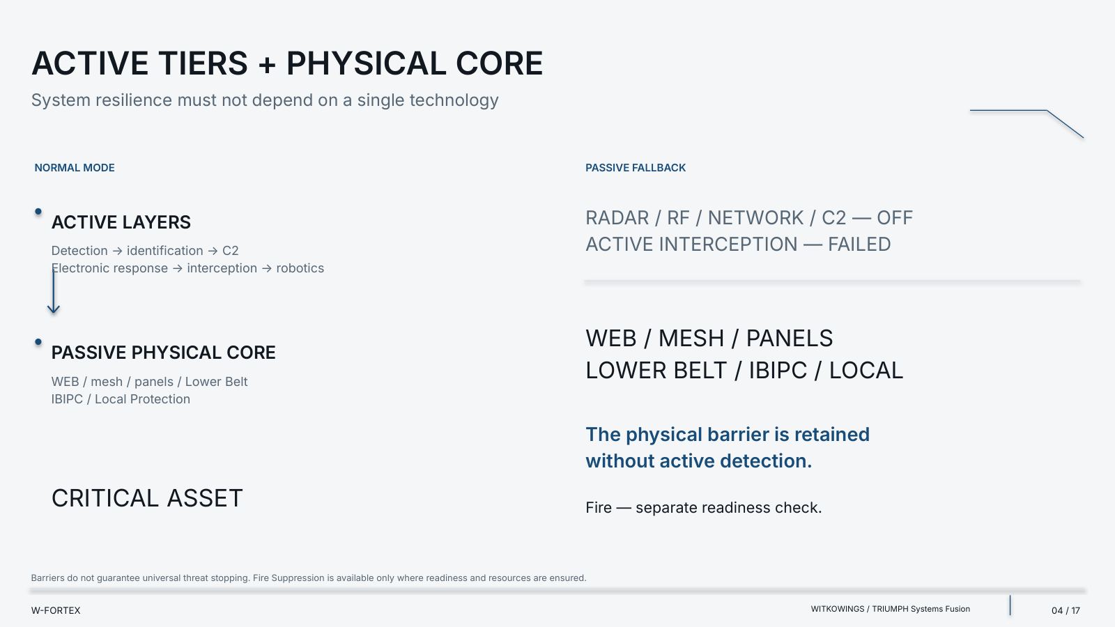
- System resilience must not depend on a single technology — active layers and the passive physical core work together
- Active layers — Detection → identification → C2; Electronic response → interception → robotics
- Passive physical core — WEB / mesh / panels / Lower Belt; IBIPC / Local Protection
- Passive fallback — if Radar / RF / network / C2 and active interception fail, the physical barrier remains without active detection; Fire — a separate readiness check
- Limit — barriers do not guarantee universal threat stopping; Fire Suppression is available only when readiness and resources are ensured
- Not a single sensor. Not a single point of failure — detection → correlation → confirmation → selected response
- Radar, RF, EO / IR, Acoustic, Ground — air tracks; radio signatures; optical and thermal verification; acoustic signs; perimeter / seismic / vibration
- Correlated threat — track + confidence + operator confirmation; C2: priority → coordination → selected response
- Data quality checks and alternative channels — fusion does not eliminate common-cause failures: power, networks and synchronisation are verified separately
- C2: coordinate, do not lock in — common operating picture + an open integration contract (sensors → C2 / fusion → response)
- Replacement without breaking the architecture — RADAR A → RADAR B: the function is preserved, the interface is supported, the supplier is approved, the requirements are confirmed
- Electronic counter-UAS — early effect only in an authorised configuration
- Three steps — 01 / Detection (multi-sensor signatures); 02 / C2 / decision (classification and permissions); 03 / Electronic response (approved RF / directional means)
- If the threat continues to move — the physical W-FORTEX core: WEB → suspended protection → local hardening → secondary-effect control
- Limit — the electronic layer does not replace the physical barrier and has no universal effectiveness; frequencies, permits, EMC and safety are determined by authorised specialists
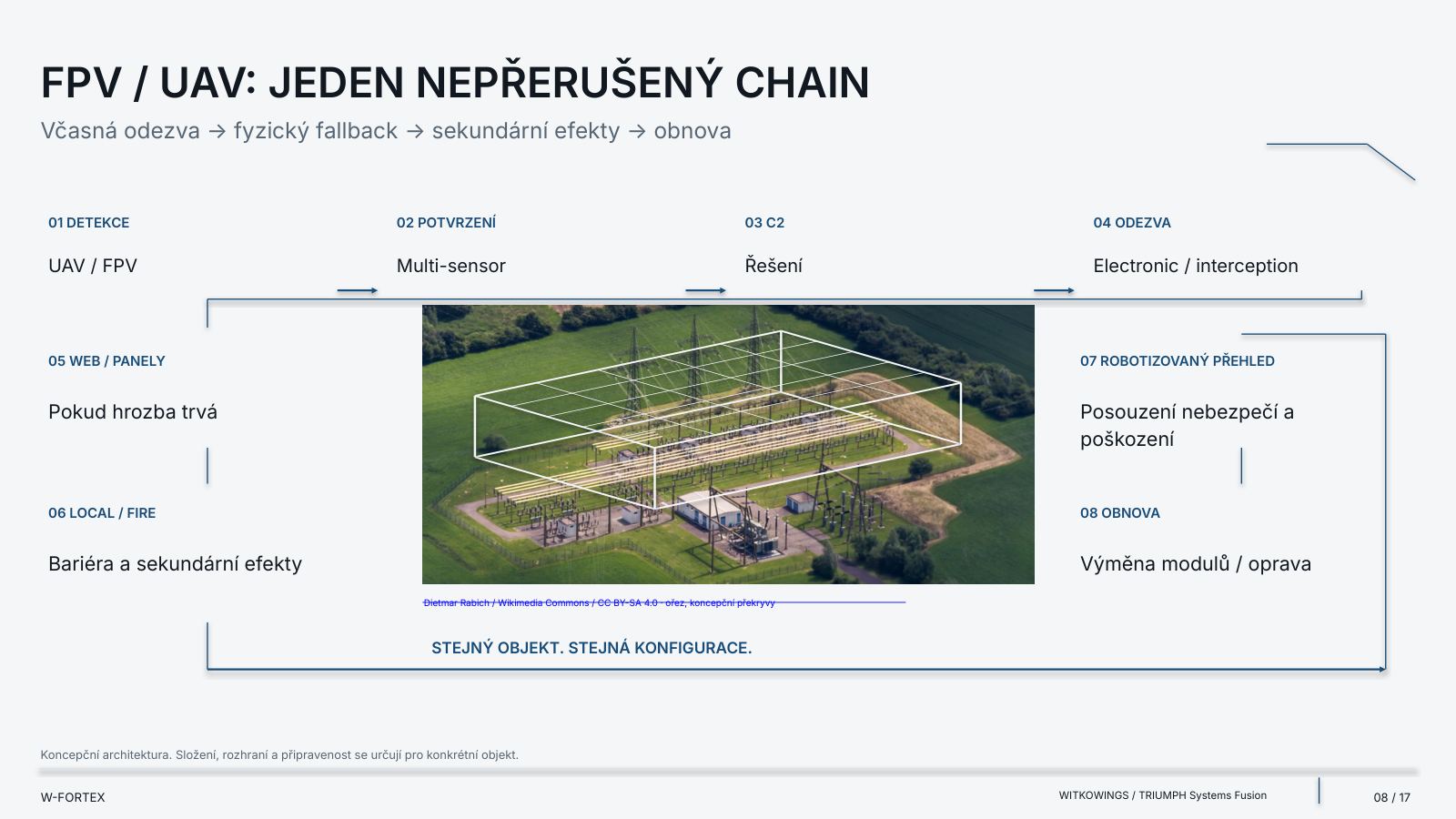
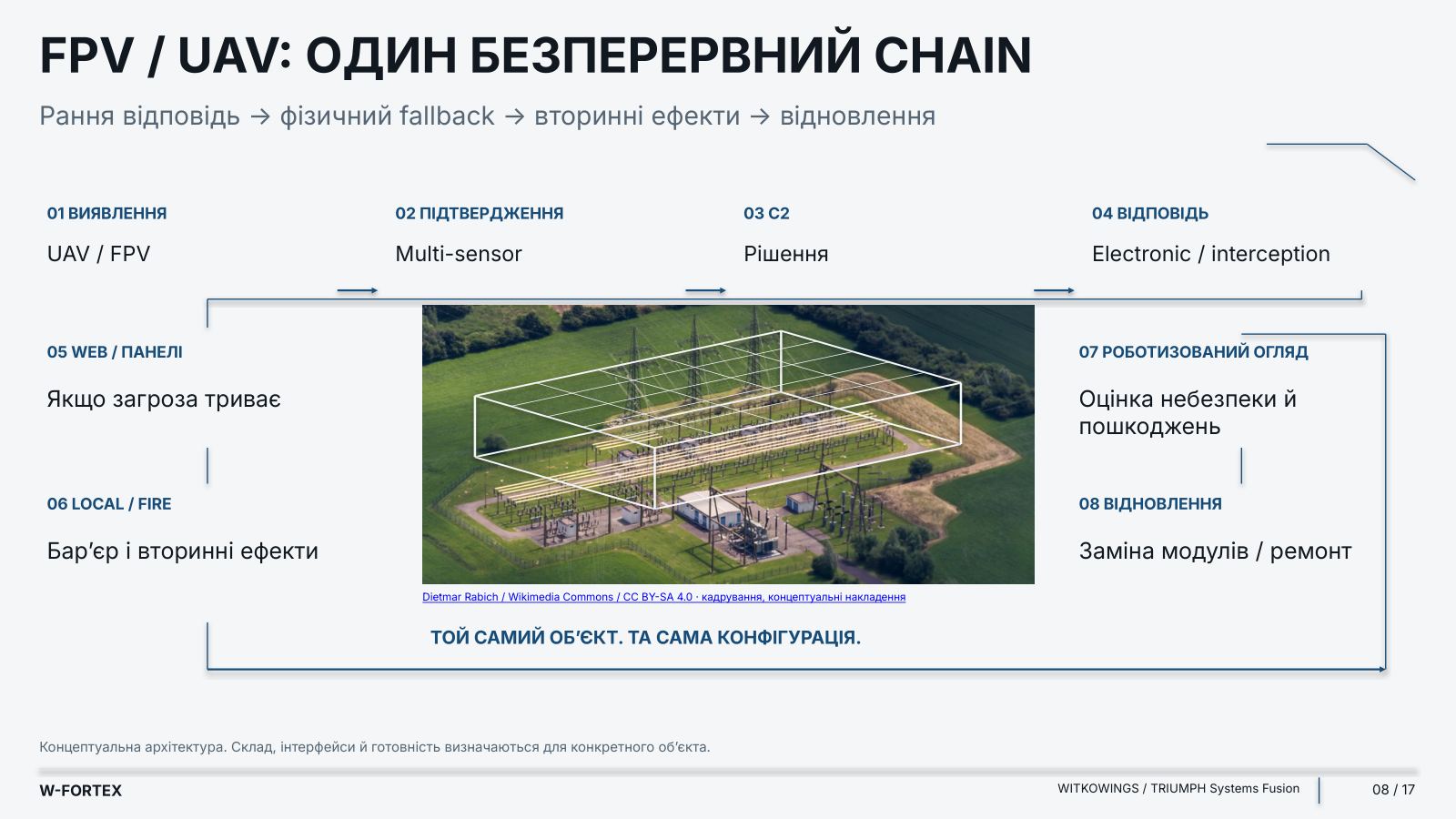
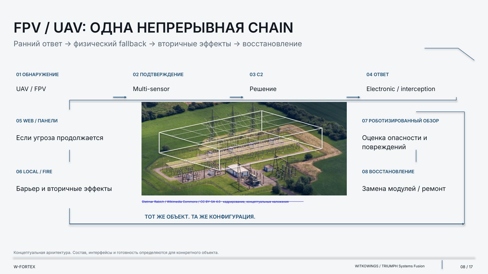
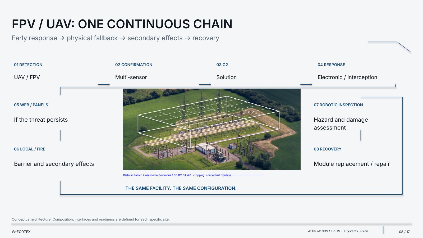
- FPV / UAV: one continuous chain — early response → physical fallback → secondary effects → recovery
- 01 Detection — UAV / FPV
- 02 Confirmation — Multi-sensor
- 03 C2 — Decision
- 04 Response — Electronic / interception
- 05 WEB / panels — if the threat persists
- 06 Local / Fire — barrier and secondary effects
- 07 Robotic inspection — hazard and damage assessment
- 08 Recovery — module replacement / repair
- Robotics: inspection before a person enters — air and ground platforms support hazard assessment and recovery
- No one enters first without a hazard assessment — remote inspection → decision by the responsible specialist
- Air robotics — reconnaissance / interceptor / counter-FPV
- Ground robotics / GRS — patrol / inspection / mobile sensors / observation; emergency response / radiation reconnaissance
- After an attack — inspection and assessment → modular repair
- Limit — the photo is an example of the UGV class, not a supplier selection and not confirmed integration of PackBot into W-FORTEX
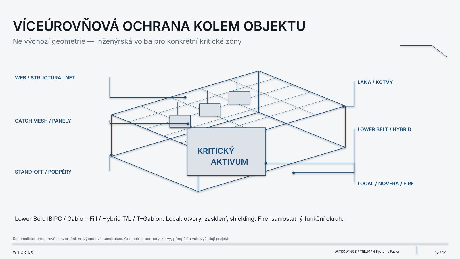
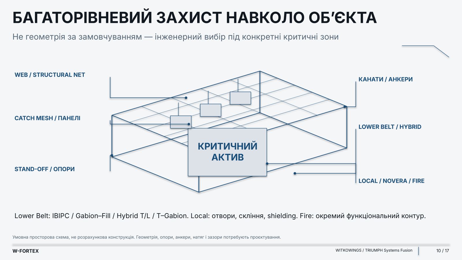
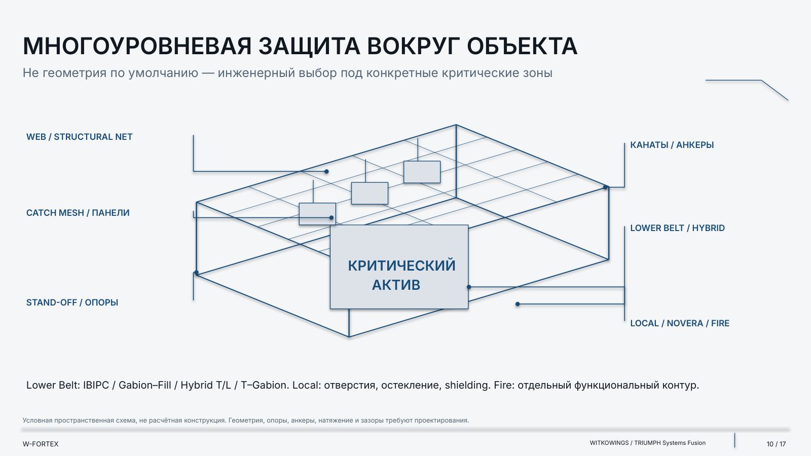
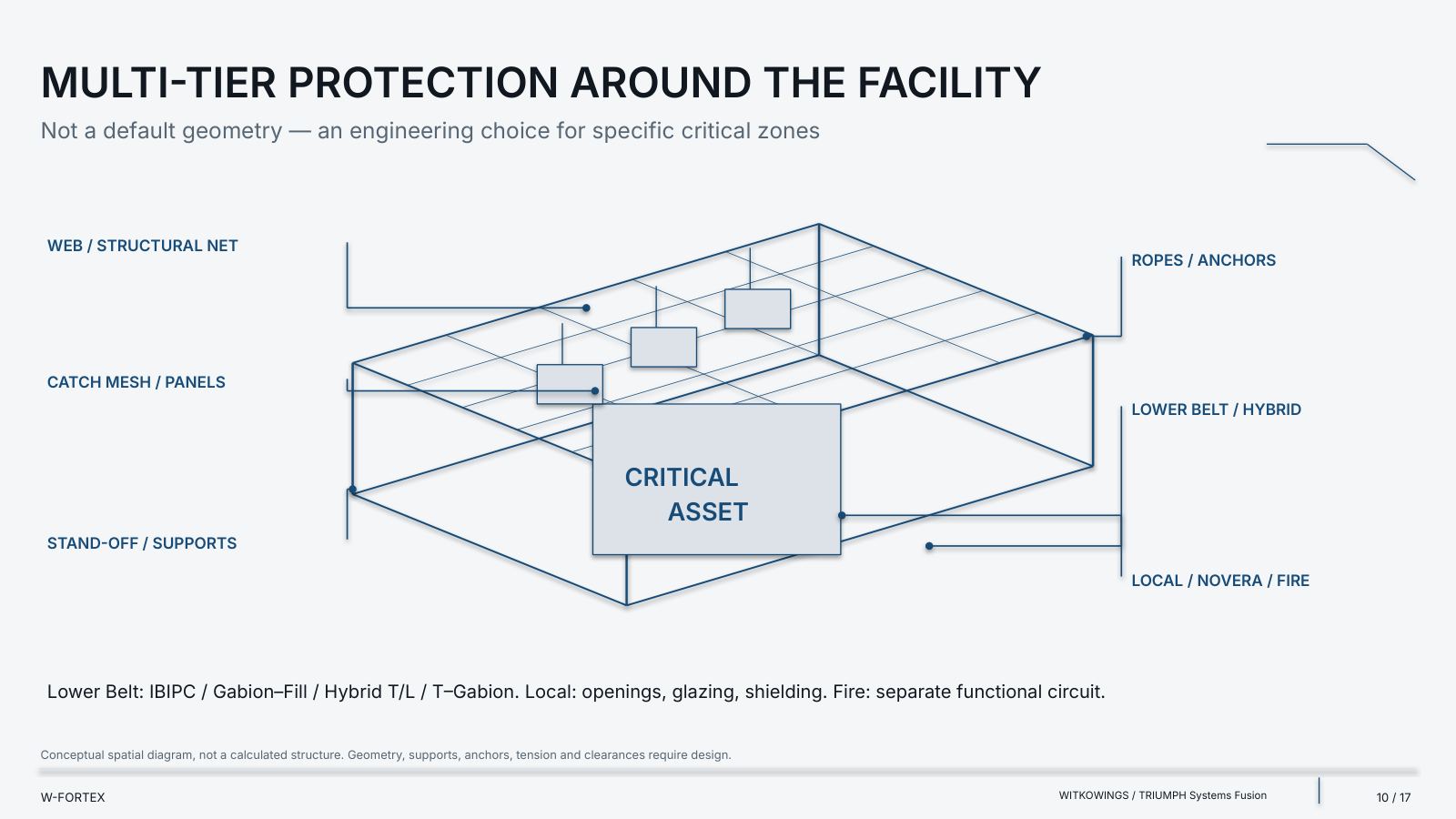
- Multi-layer protection around the facility — not default geometry, but an engineering choice for specific critical zones
- Perimeter — WEB / structural net; catch mesh / panels; stand-off / supports; cables / anchors
- Lower Belt — IBIPC / Gabion–Fill / Hybrid T/L / T–Gabion
- Local — openings, glazing, shielding; NOVERA; Fire — a separate functional circuit
- Limit — a conceptual spatial diagram, not a calculated structure: geometry, supports, anchors, tension and clearances require design
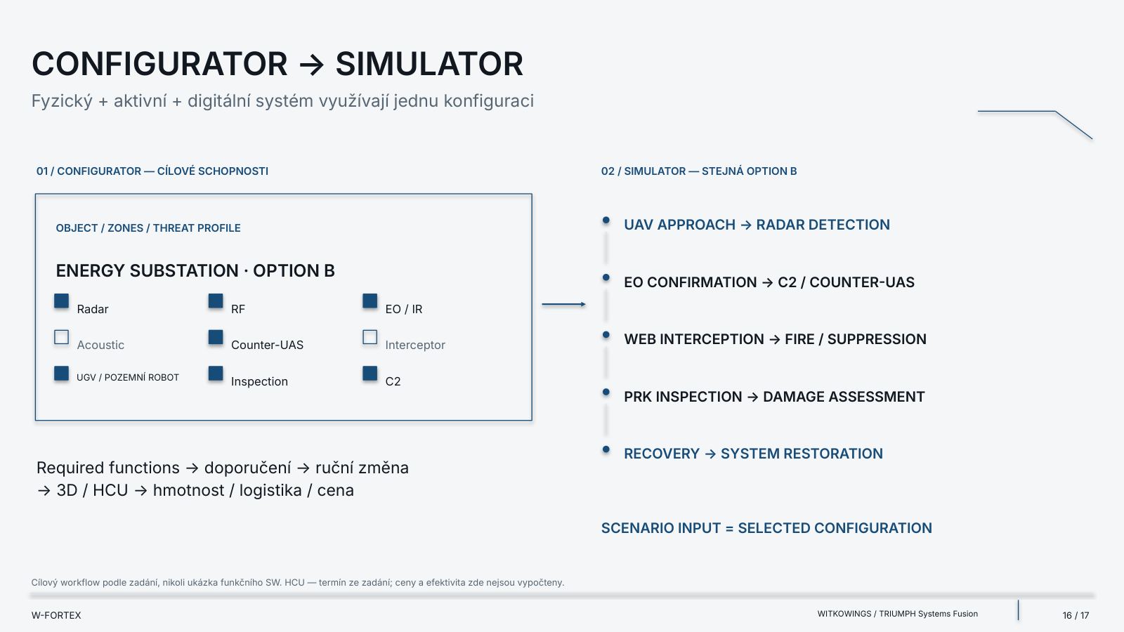
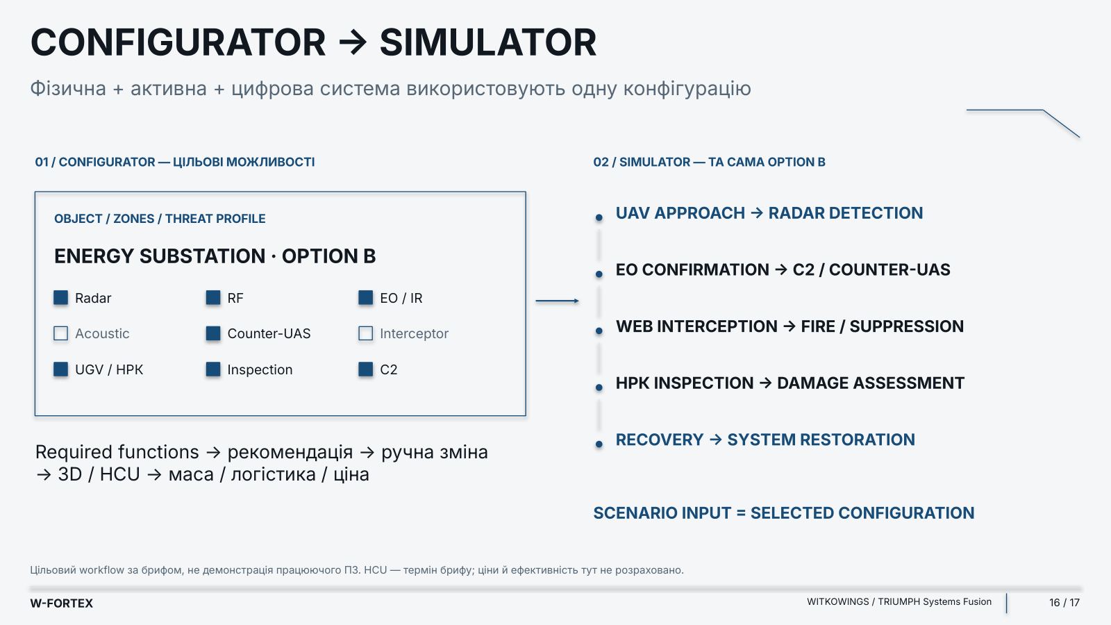
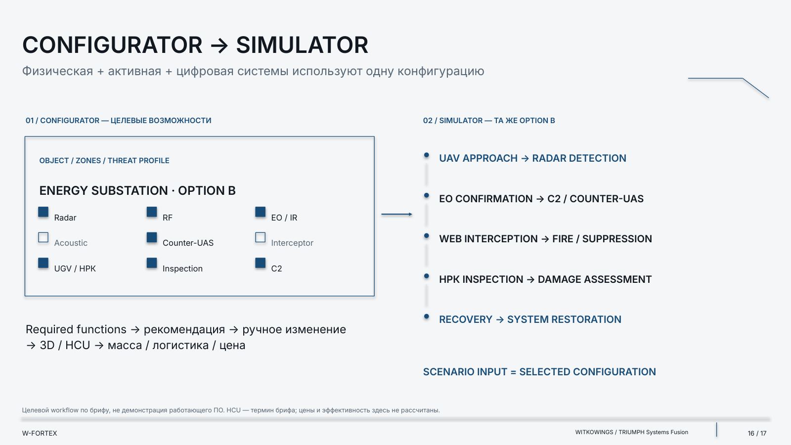
Configurator → Simulator
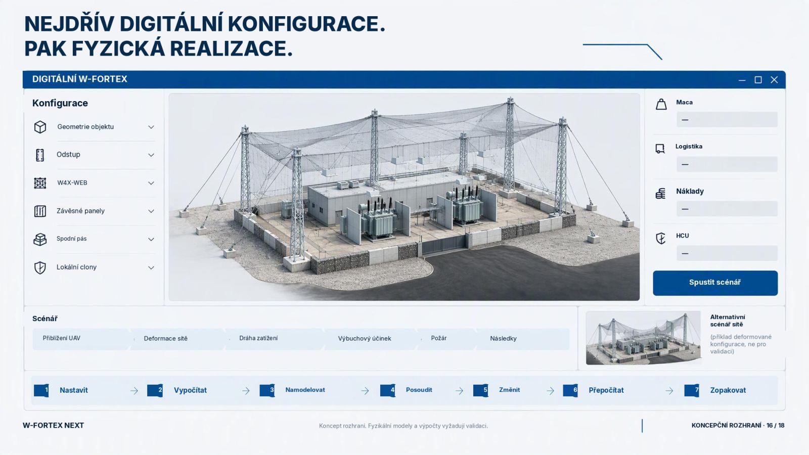
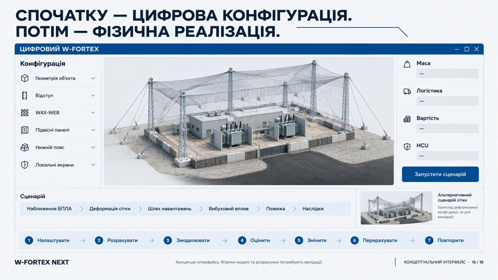
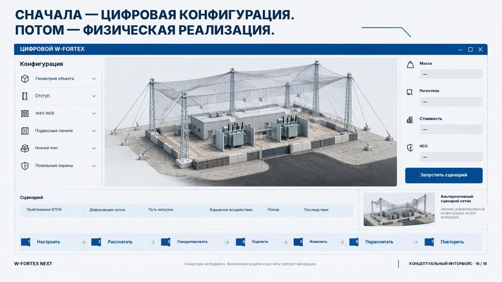
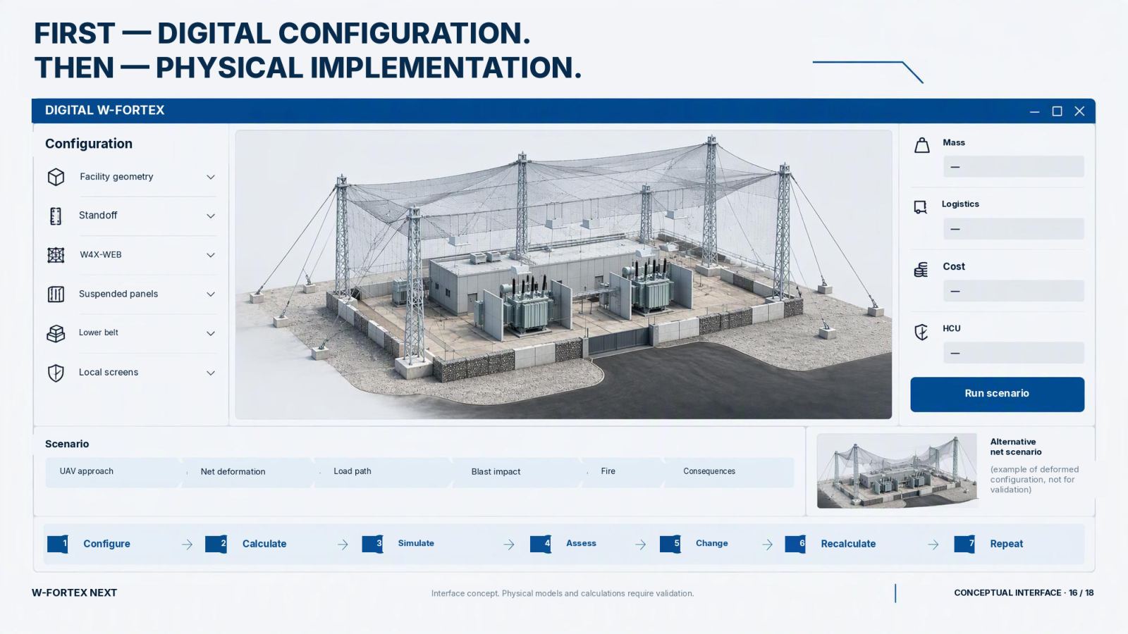
The physical + active + digital system uses a single configuration. First — the digital configuration. Then — the physical implementation. A target workflow per the brief, not a demonstration of working software. HCU is a brief term; prices and effectiveness are not calculated here.
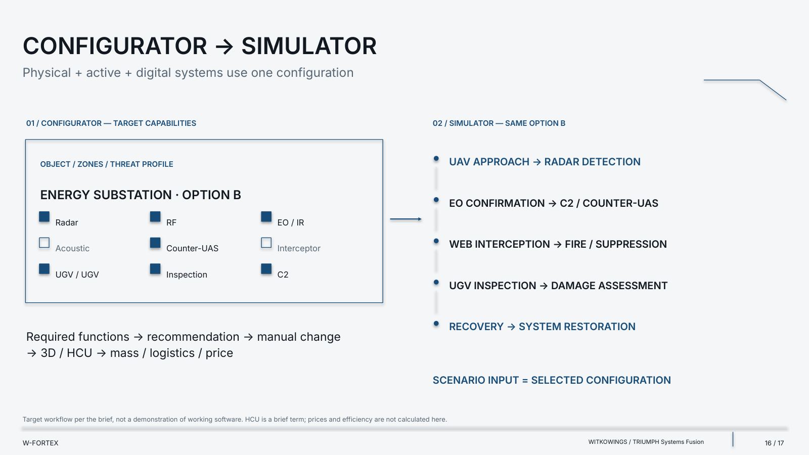
- 01 / Configurator — target capabilities — object / zones / threat profile; example: Energy Substation · Option B
- Functions to select — Radar, RF, EO / IR, Acoustic, Counter-UAS, Interceptor, UGV / GRS, Inspection, C2
- Workflow — Required functions → recommendation → manual change → 3D / HCU → mass / logistics / price
- 02 / Simulator — the same Option B
- UAV approach → radar detection
- EO confirmation → C2 / Counter-UAS
- WEB interception → Fire / suppression
- GRS inspection → damage assessment
- Recovery → system restoration
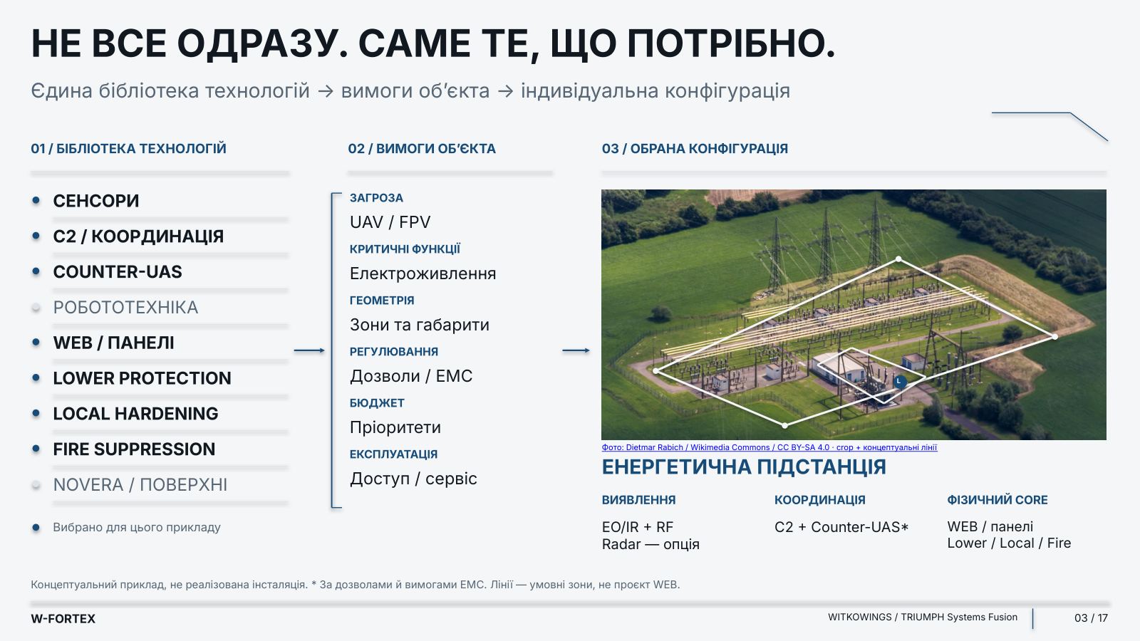
- Rule — scenario input = selected configuration
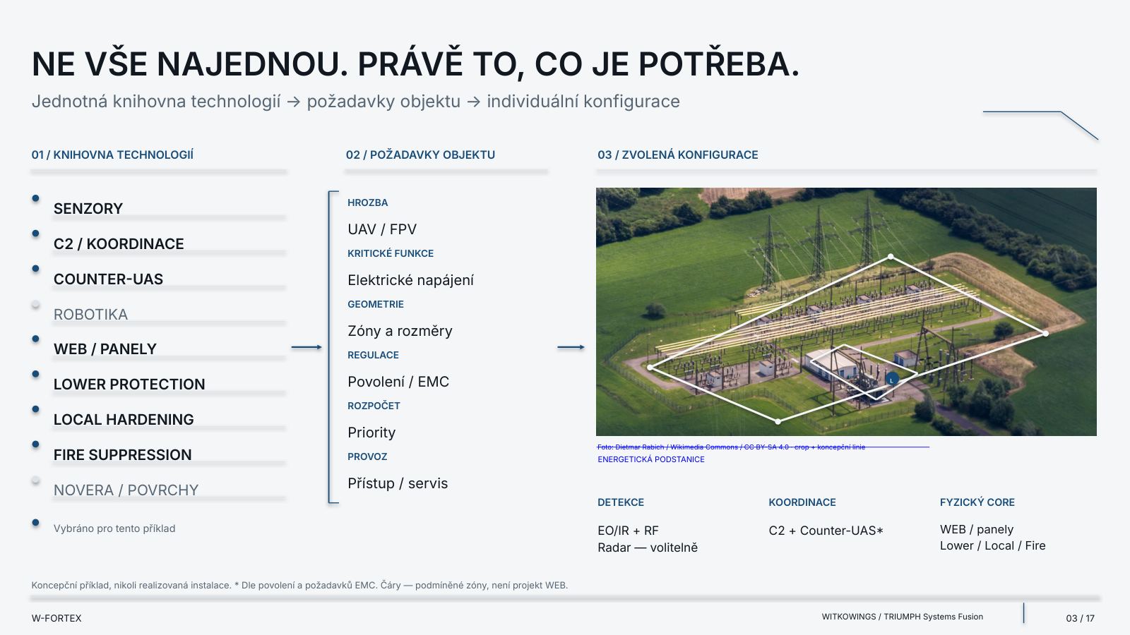
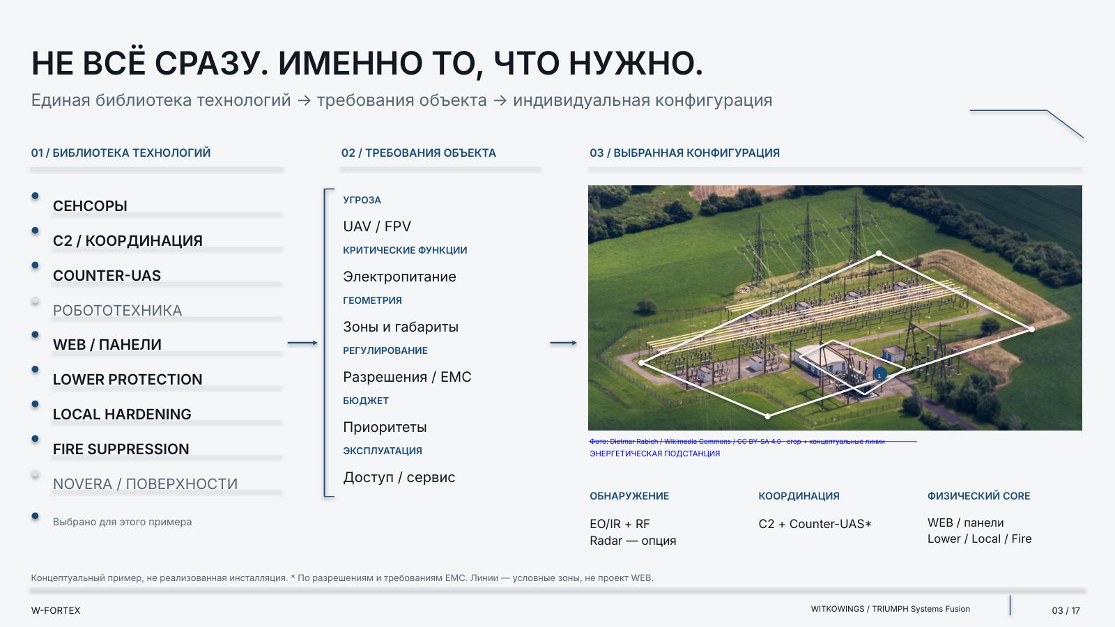
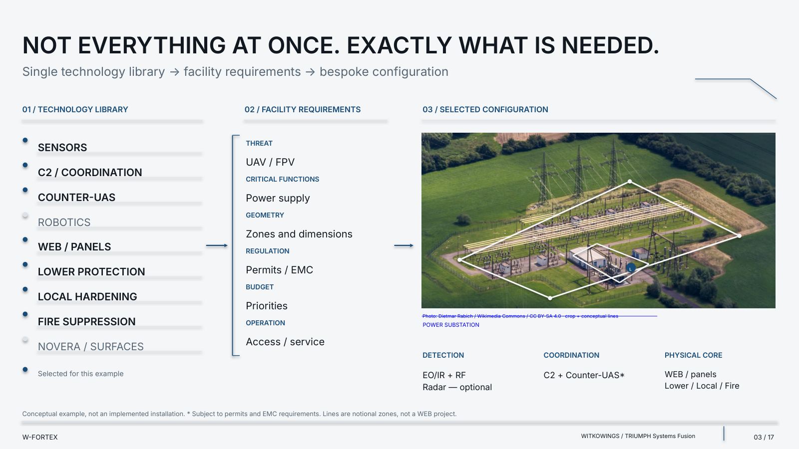
- Threat — UAV / FPV
- Critical functions — power supply
- Geometry — zones and dimensions
- Regulation — permits / EMC
- Budget — priorities
- Operation — access / service
- Example — Energy substation: EO/IR + RF detection (radar — optional); C2 + Counter-UAS* coordination; physical core: WEB / panels, Lower / Local / Fire
| Integration field | What we verify |
|---|---|
| FUNCTION | The required function and the requirements of the specific facility |
| SOURCE | Supplier, product, version and support |
| INTERFACE | Protocol, data, timing, cybersecurity and degraded mode |
| EVIDENCE STATUS | Tests, qualification, limits of application |
| INTEGRATION STATUS | Planned → tested → accepted; the status is not substituted |
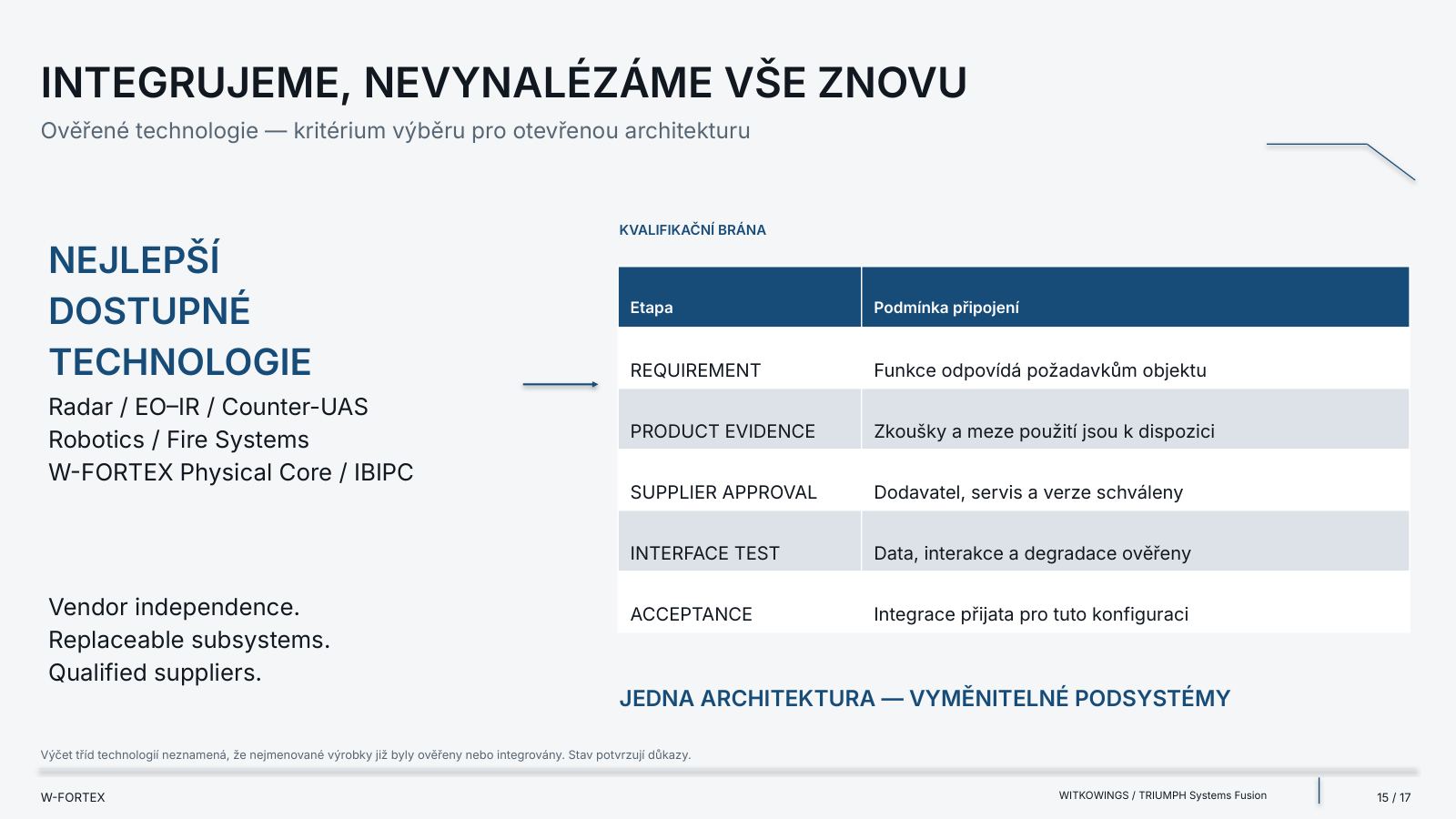
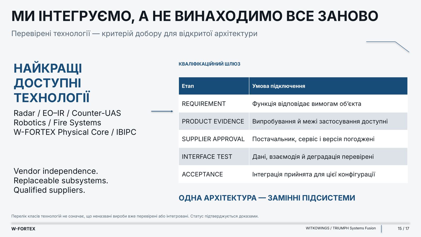
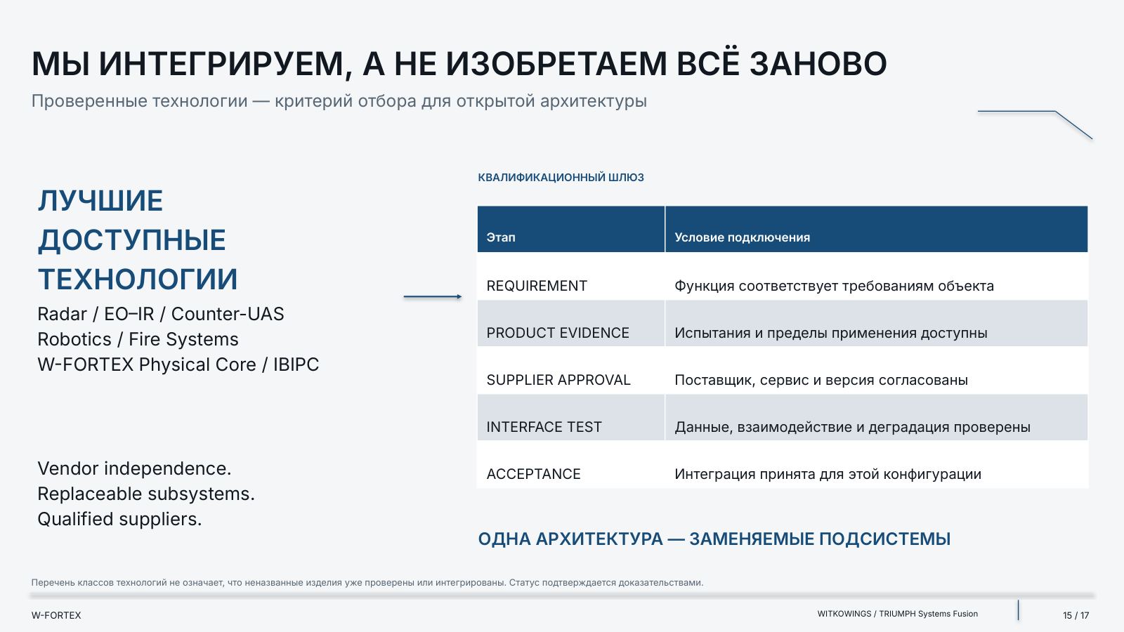
| Stage | Condition for connection |
|---|---|
| REQUIREMENT | The function meets the facility’s requirements |
| PRODUCT EVIDENCE | Tests and limits of application are available |
| SUPPLIER APPROVAL | Supplier, service and version are approved |
| INTERFACE TEST | Data, interaction and degradation are verified |
| ACCEPTANCE | The integration is accepted for this configuration |
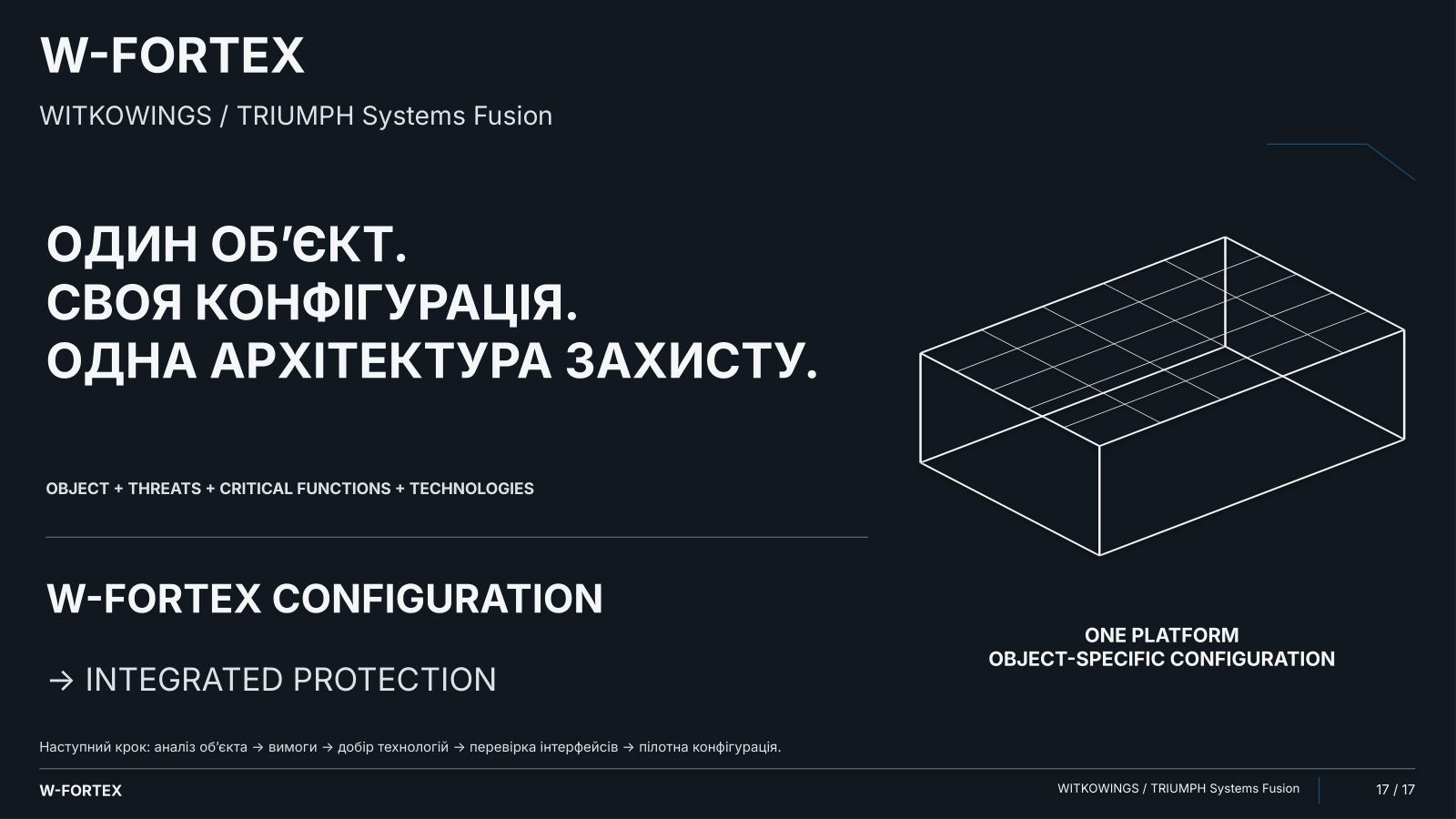
We integrate rather than reinvent everything. Best available technologies: Radar / EO–IR / Counter-UAS, Robotics / Fire Systems, W-FORTEX Physical Core / IBIPC. Vendor independence. Replaceable subsystems. Qualified suppliers. One architecture — replaceable subsystems.
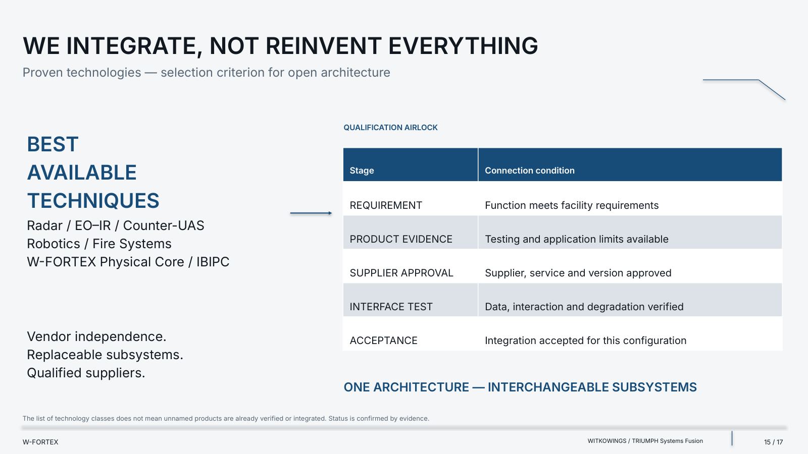
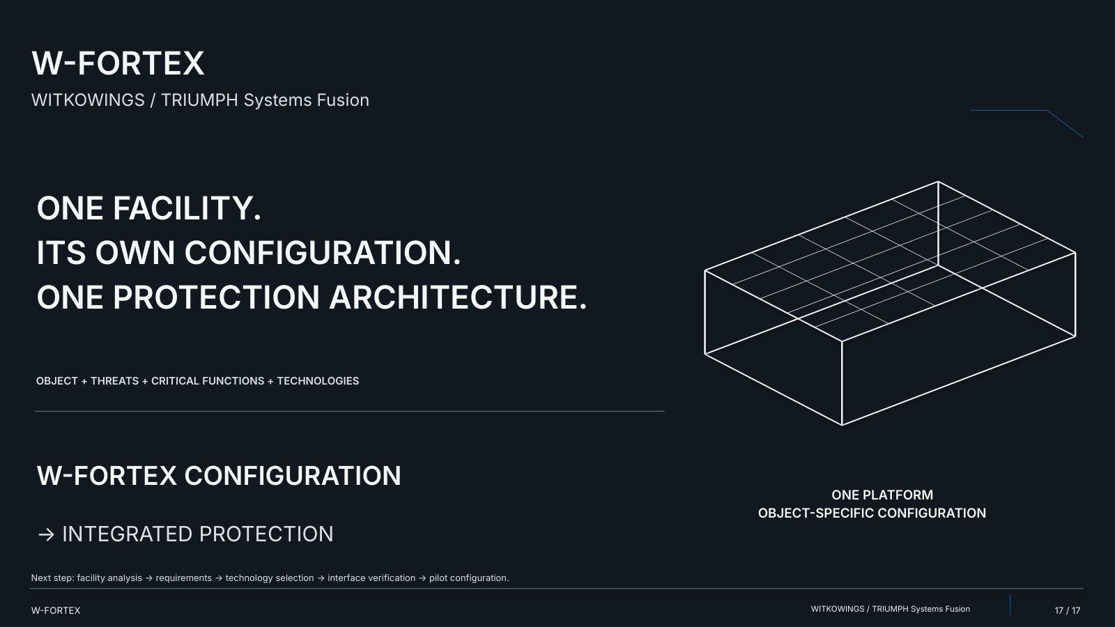
A list of technology classes does not mean that unnamed products have already been verified or integrated. Status is confirmed by evidence. Next step: facility analysis → requirements → technology selection → interface verification → pilot configuration.
IIIShelters and CBRN Resilience
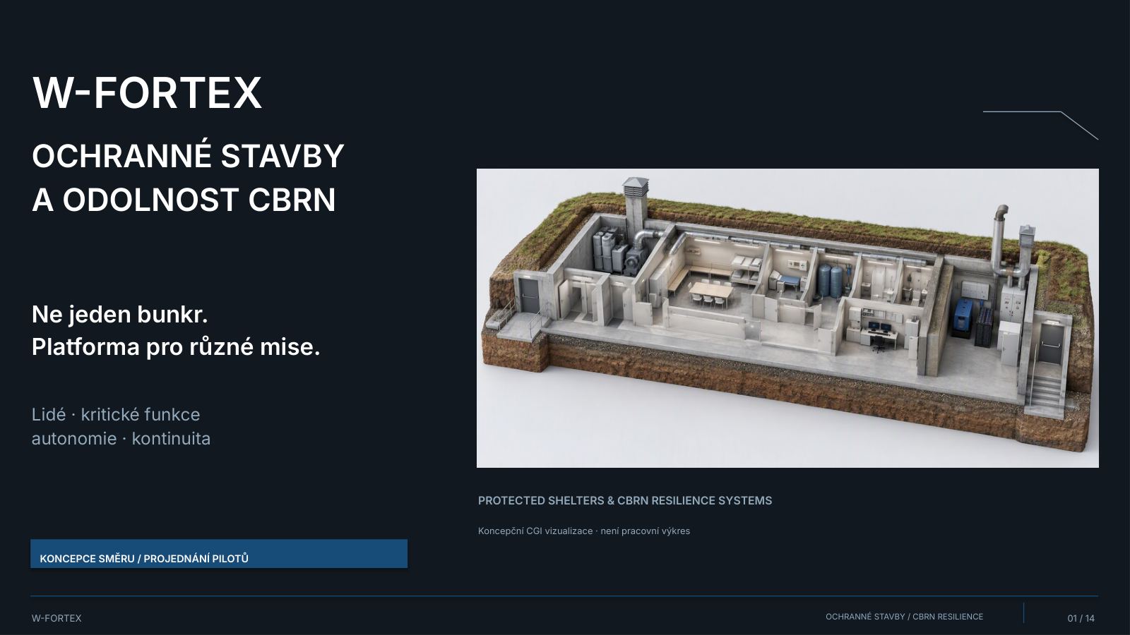
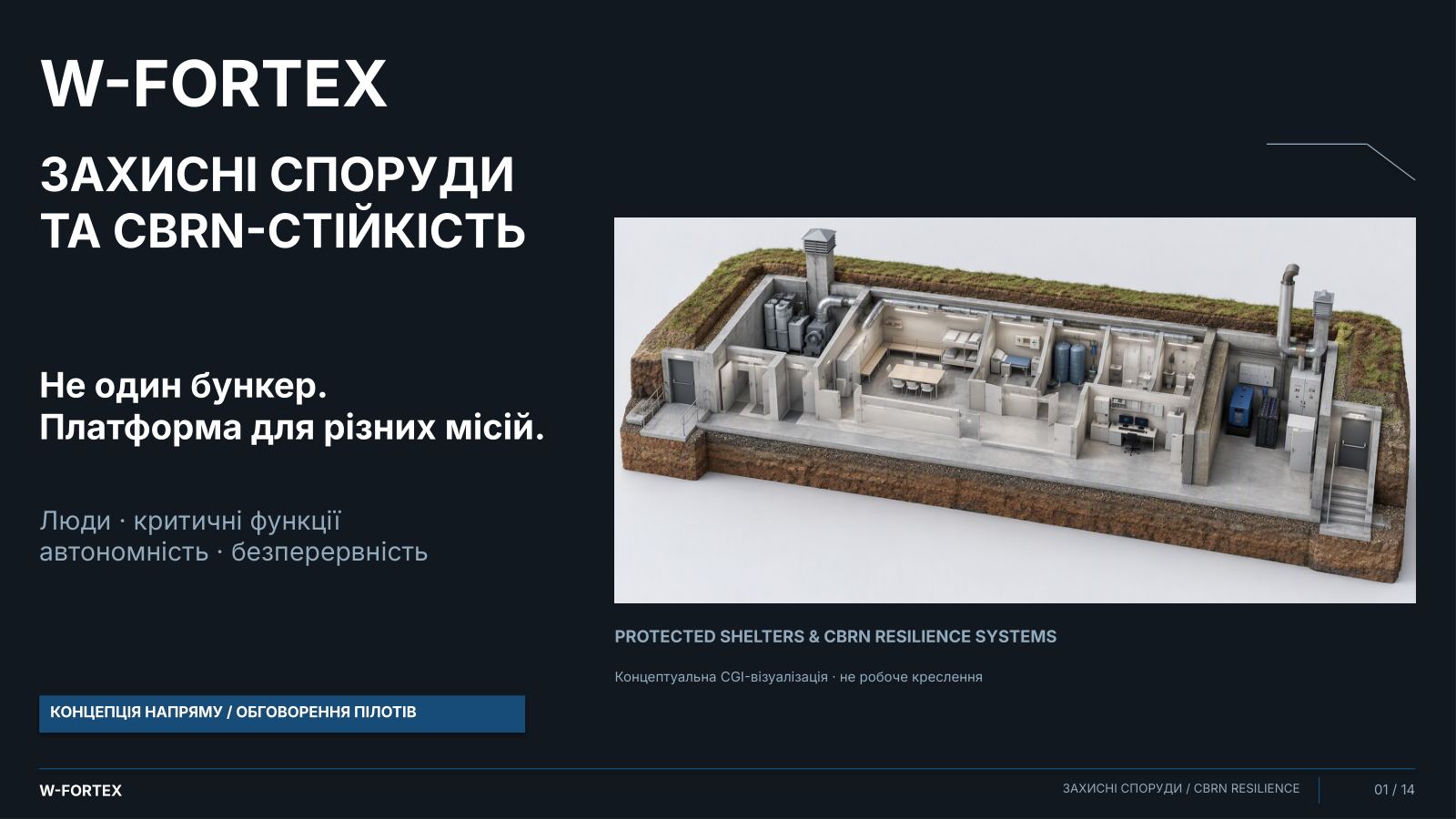
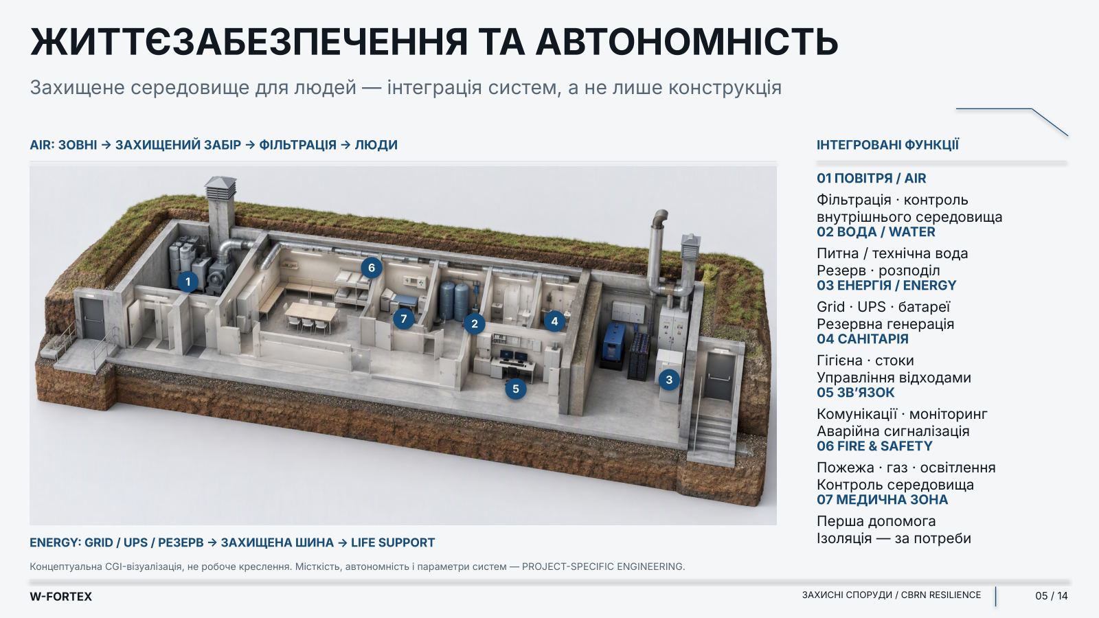
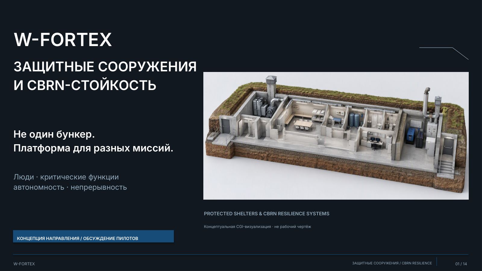
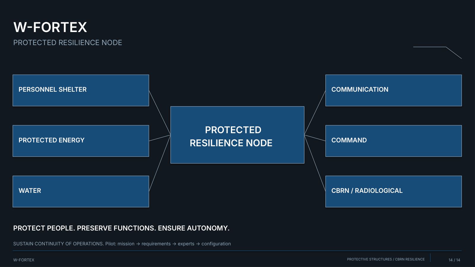
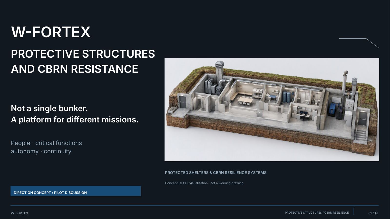
Continuity requires a protected environment for people and technical functions. Not a single bunker. A platform for different missions: people · critical functions · autonomy · continuity. Conceptual CGI visualisation · not a working drawing.
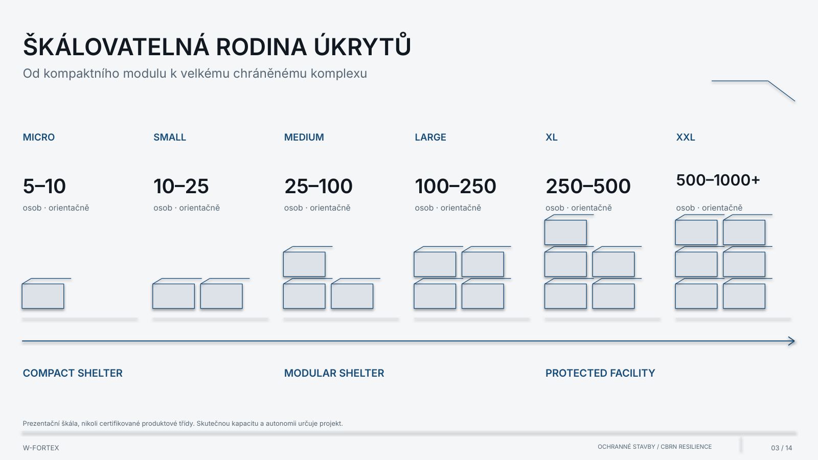
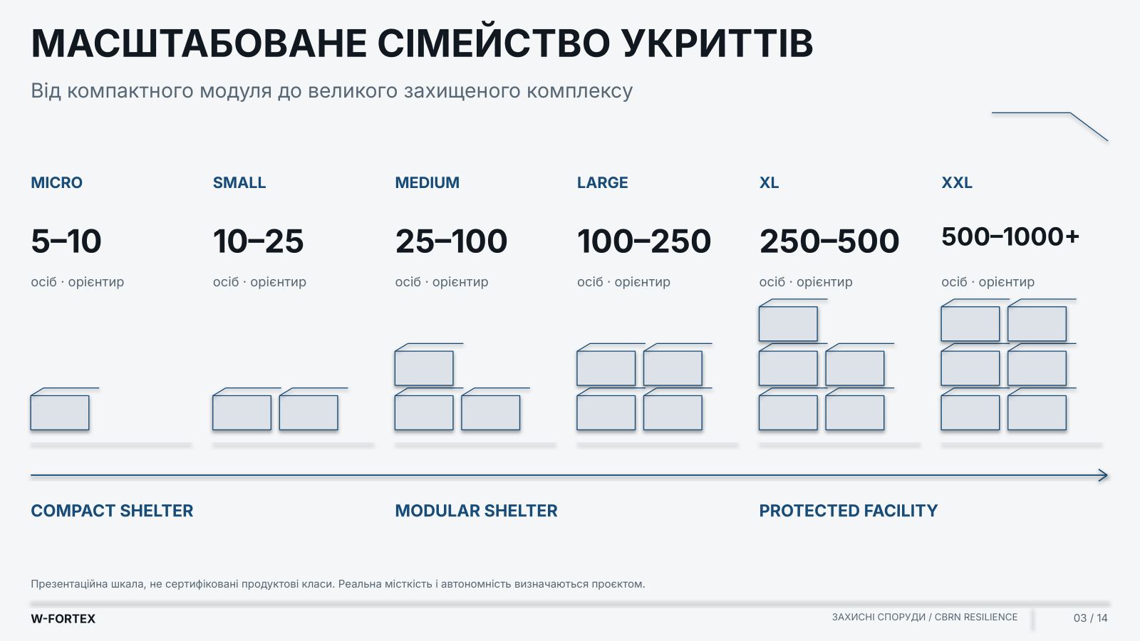
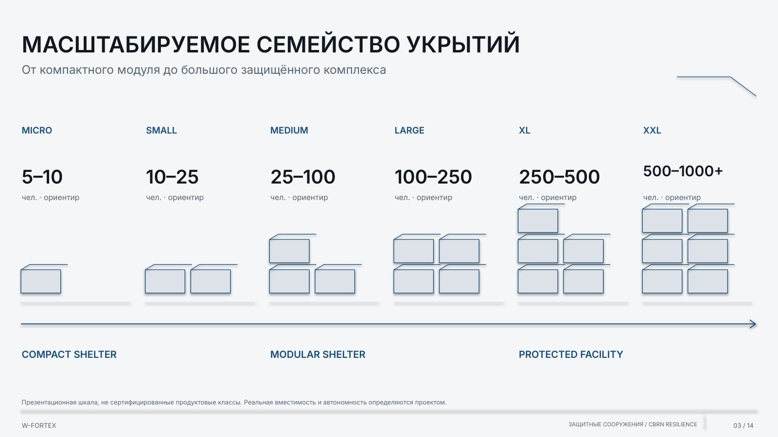
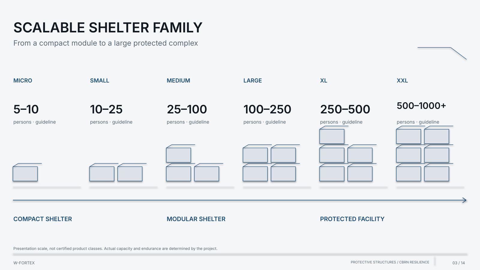
| Class | Capacity, persons · guideline |
|---|---|
| MICRO | 5–10 |
| SMALL | 10–25 |
| MEDIUM | 25–100 |
| LARGE | 100–250 |
| XL | 250–500 |
| XXL | 500–1,000+ |
A scalable family of shelters — from a compact module to a large protected complex (COMPACT SHELTER · MODULAR SHELTER · PROTECTED FACILITY). A presentation scale, not certified product classes. Actual capacity and autonomy are determined by the project.
| User | Group | Examples |
|---|---|---|
| 01 / CIVIL | Civil shelters | Population · municipal infrastructure |
| 02 / SCHOOL | Educational institutions | Schools · universities · children’s facilities |
| 03 / MEDICAL | Medical and public sector | Hospitals · social and government institutions |
| 04 / INDUSTRIAL | Industrial personnel | Manufacturing · oil and gas sector |
| 05 / ENERGY | Energy personnel | Power plants · substations · thermal power |
| 06 / NUCLEAR | Nuclear / radiological facilities | Research institutions · materials · radioactive waste |
| 07 / COMMAND | Emergency management | Operational teams · protected control rooms |
| Focus | Civil / schools | Industry | Energy | Nuclear / Radiological |
|---|---|---|---|---|
| People and access | Capacity · safe access; clear evacuation | Shift teams; technical access | Personnel; operational teams | Specialised personnel; controlled access |
| Critical function | Sanitation · ventilation; medical support | Communications; emergency management | Control · backup generation; technical continuity | Emergency safety functions; radiation monitoring |
| Special modules | Life support; medical area — as needed | Emergency energy; command · communication | Cogeneration · batteries; protected technical modules | CBRN · dosimetry; protected ventilation |
| Design logic | User groups; accessibility · evacuation | Facility operating mode; technical zone boundaries | Critical loads; redundancy | Safety case · zone control; specialised expertise |
- A modular protected structure — the material and the systems’ composition are chosen for the mission, not the other way round
- Input requirements — mission and capacity; autonomy; threat profile; CBRN requirements; site conditions; energy needs
- Selected modules — a configuration for a specific facility: structure, air / CBRN, energy, water, sanitation, medical, command, communications, technical
- W-FORTEX Facility — a protected environment for people and functions; project-specific
- Material by mission — conventional / monolithic / precast reinforced concrete · high-performance concrete
- Options — IBIPC / UHPFRC · steel · composite · hybrid systems
- Execution — above ground · earth-bermed · partially or fully buried
- Priorities are shown, not a rigid kit — functions can be combined; all characteristics are determined by the project
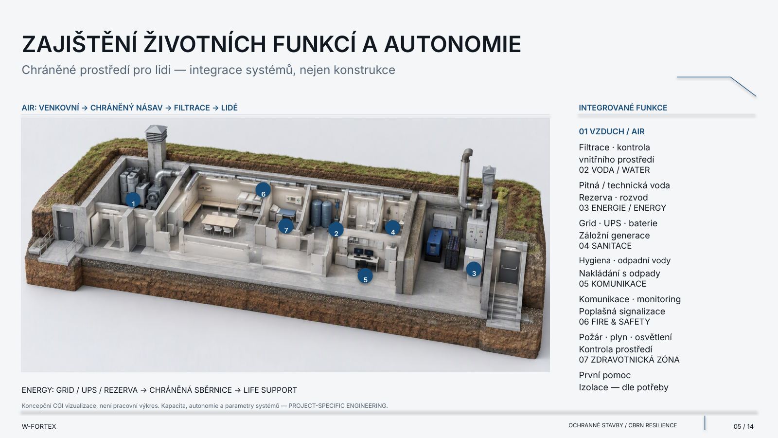
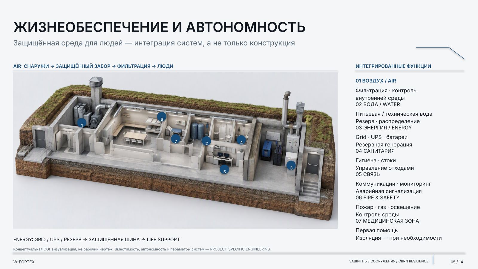
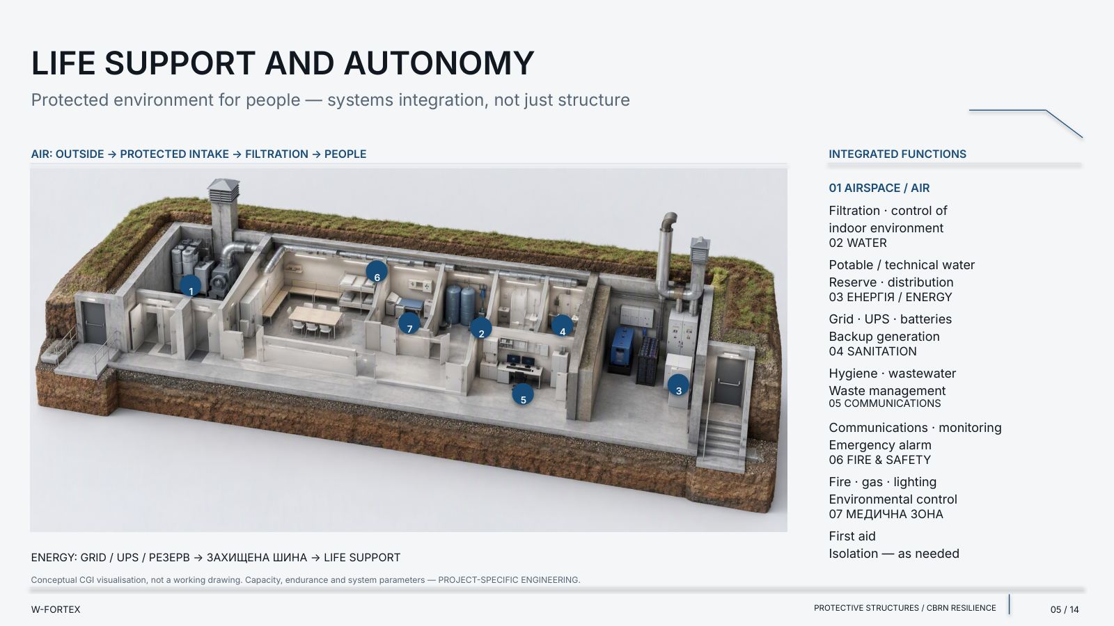
Life support and autonomy — systems integration, not just the structure. Air: outside → protected intake → filtration → people. Energy: grid / UPS / reserve → protected bus → life support. Capacity, autonomy and system parameters — project-specific engineering.
CBRN Configuration and Protected Resilience
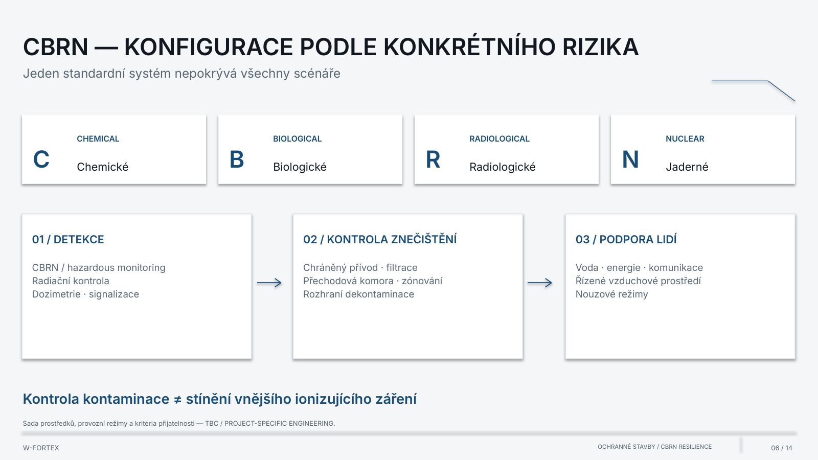
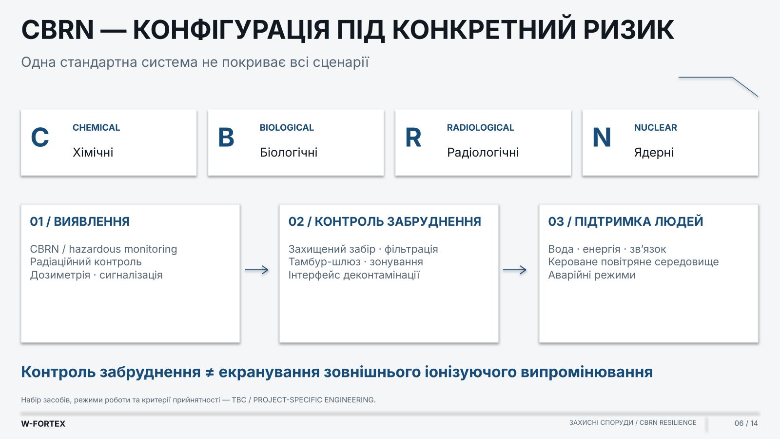
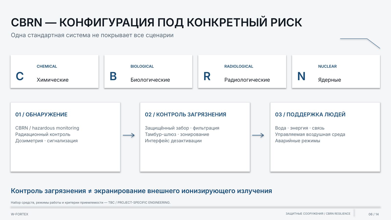
CBRN — a configuration for a specific risk. One standard system does not cover all scenarios. The set of means, operating modes and acceptance criteria — TBC / project-specific engineering.
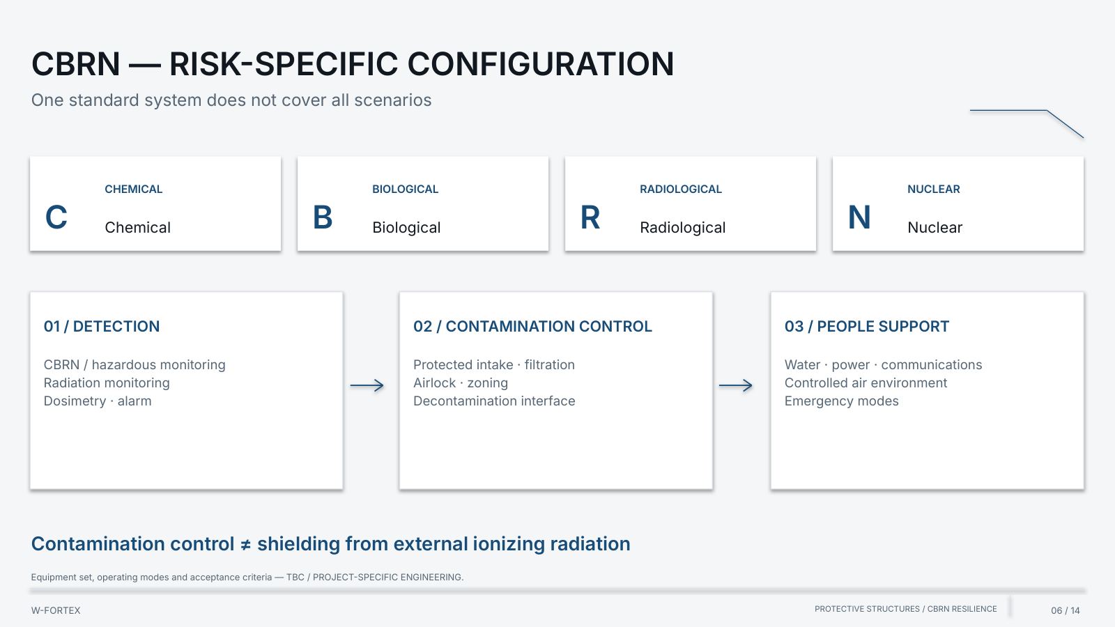
- 01 / Detection — CBRN / hazardous monitoring; radiation monitoring; dosimetry · alarm
- 02 / Contamination control — protected intake · filtration; airlock vestibule · zoning; decontamination interface
- 03 / Support for people — water · energy · communications; controlled air environment; emergency modes
Contamination control ≠ shielding against external ionising radiation.
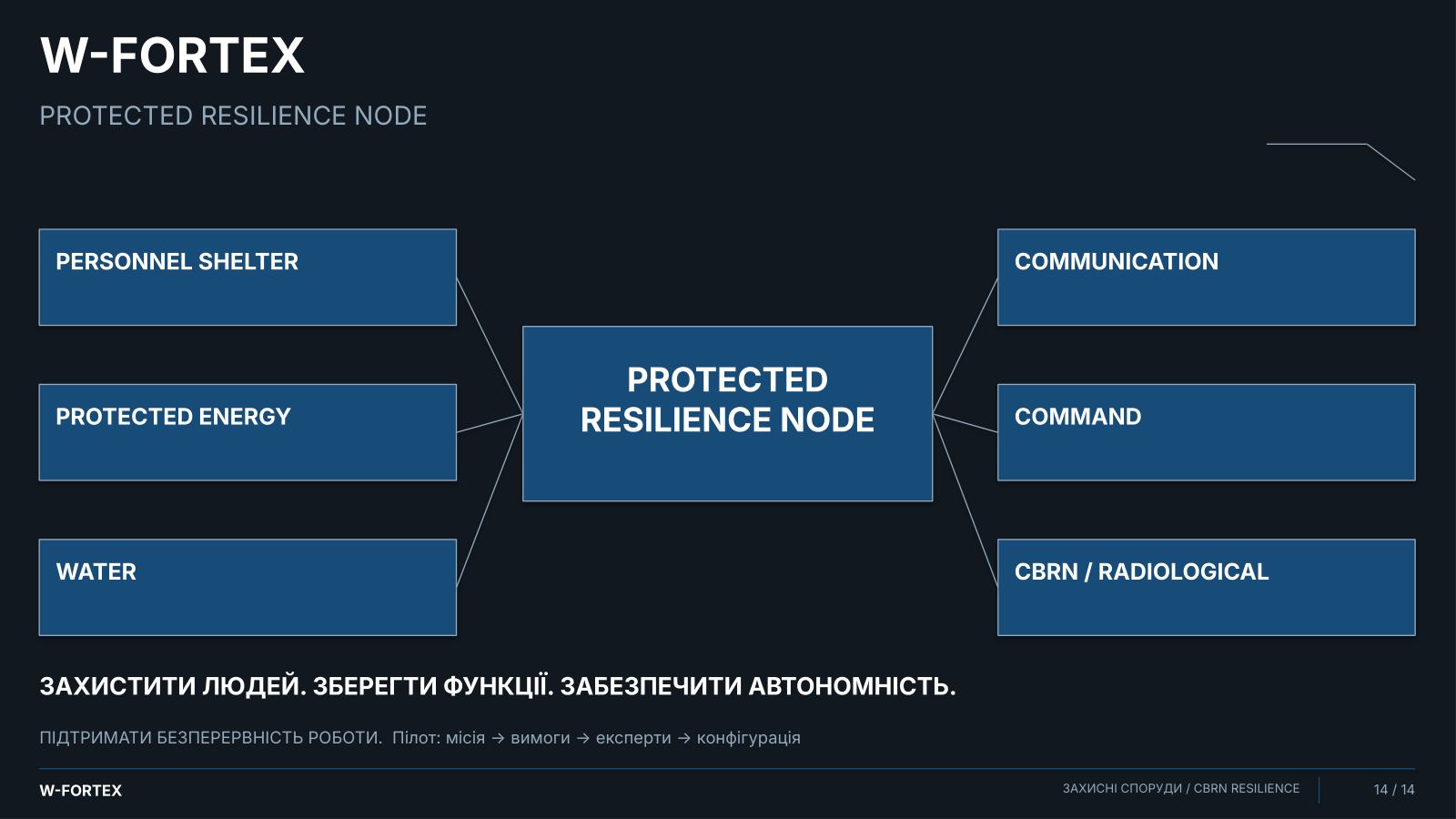
- Nuclear and radiological integration — a protected environment to support critical safety functions
- Emergency personnel — specialised personnel; protected technical rooms; emergency management; controlled access
- Functions — power (emergency power), cooling (cooling interfaces), control (protected control), monitoring (radiation · dosimetry), communication (emergency communications), access (zone / access control), emergency response (response support)
- Limit — integration into the facility’s safety case; not automatic nuclear qualification or certification of W-FORTEX
- Ventilation and filtration — a critical subsystem: integrated control of air and isolation modes
- Chain — external environment → protected intake → filtration → controlled environment → personnel
- Control — monitoring → mode control → alarm → personnel actions
- Modes and redundancy — emergency ventilation · redundancy; pressure control — where required
- Isolation and exhaust — controlled air removal; control of contamination crossflow
- Limit — generator: separate design of combustion and exhaust; filter classes, flow rate and pressure — TBC / project-specific
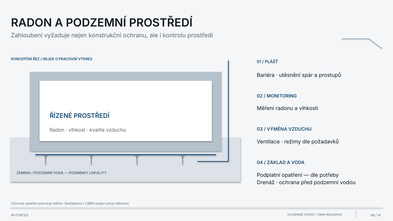
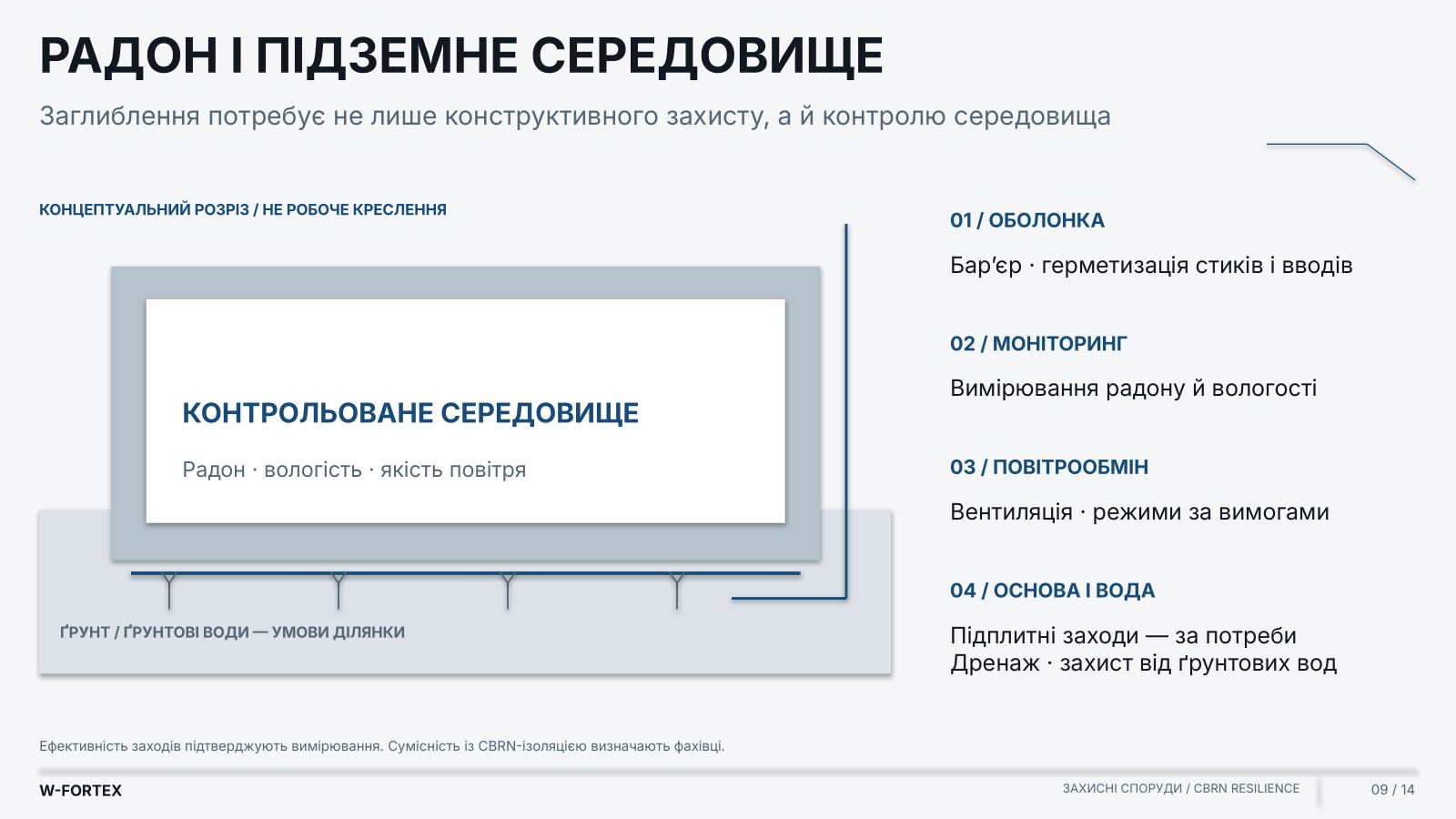
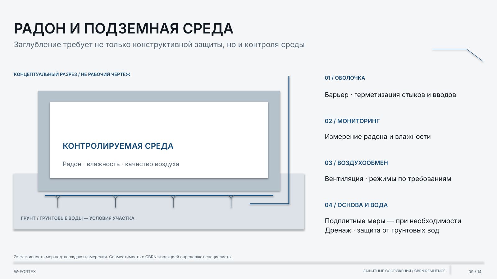
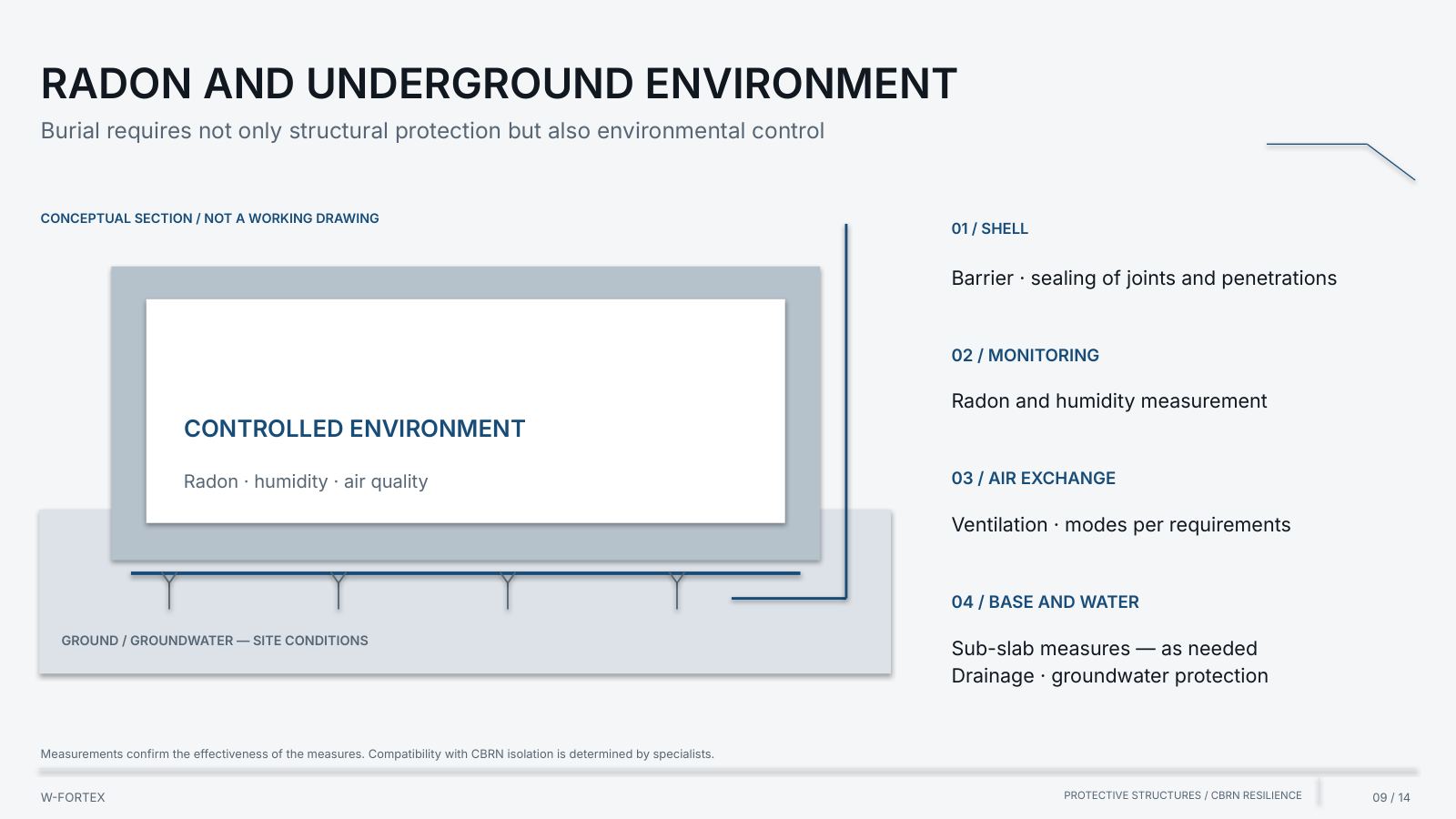
- Radon and the underground environment — burial requires not only structural protection but also environment control
- 01 / Envelope — barrier · sealing of joints and penetrations
- 02 / Monitoring — radon and humidity measurement
- 03 / Air exchange — ventilation · modes as required
- 04 / Base and water — sub-slab measures — as needed; drainage · groundwater protection
- Limit — the effectiveness of measures is confirmed by measurements; compatibility with CBRN isolation is determined by specialists
- Suitability for long-term occupancy — preserve not only life, but also support people’s ability to work
- Logic — duration of stay → resources → space → operating modes
- Limit — capacity, occupancy conditions and autonomy time — per calculation for the specific facility
- Protected energy and decentralisation — we protect not only people, we protect the facility’s function
- A centralised node — a concentration of dependencies; instead, modules: A / Generation (backup generation · cogeneration / micro-CHP), B / Storage (batteries · UPS · protected distribution), C / Control (control · communications · technical reserves)
- Critical functions — life support; pumps · water; control · communications
- Limit — redundancy and autonomy per scenarios and calculation; combustion / exhaust paths are separate from ventilation for people
- Scientific and technical cooperation — for complex facilities, a protective structure is an integrated engineering system
- Facility requirements — operator · safety case; mission · risks
- W-FORTEX Engineering — architecture; systems integration
- Specialised institutions — industry institutes; scientific expertise
- CBRN / Nuclear experts — radiation safety; physical protection
- System suppliers — air · energy; monitoring · communications
- Limit — a model of the required involvement of competencies; specific partners, contracts and roles are agreed for the project
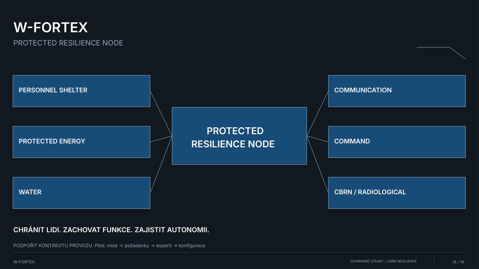
Protect people. Preserve functions. Ensure autonomy. Support operational continuity. Pilot: mission → requirements → experts → configuration.
IVIBIPC — Technical Annex
From concept to specific products and verifiable source data. UHPFRC technology, modular protective elements, drawings, tests and primary documents. IBIPC is one of the material directions of W-FORTEX, not a mandatory basis for all solutions.
- IBIPC in the W-FORTEX architecture — one of the high-performance technologies, not the only material in the system
- Place in the architecture — W-FORTEX (modular protection architecture) → Lower Protective Belt, Local Hardening, IBIPC / UHPFRC (high-performance concrete elements)
- Selection criteria — criticality · required protection level · available footprint · transport and installation · verified configuration
- Limit — a conceptual integration of W-FORTEX per the customer’s brief; not a test result
- IBIPC: technology profile — Institute of Blast & Impact Proof Concrete; the name IBIPC is retained as a technology designation within W-FORTEX
- Material — UHPFRC (Ultra High Performance Fiber Reinforced Concrete): ultra-high-performance fibre-reinforced concrete
- Development — the catalogue links the development to the Czech Technical University in Prague, the University of Defence and the Military Research Institute
- Ministry of Defence — the letter cites research cooperation and contractual interaction
- CTU Prague — the elements were developed jointly with CTU Prague, the University of Defence and the Military Research Institute; protected by international patent rights
- University of Defence / VVÚ — Faculty of Military Technology; Military Research Institute: final tests, reports, certification
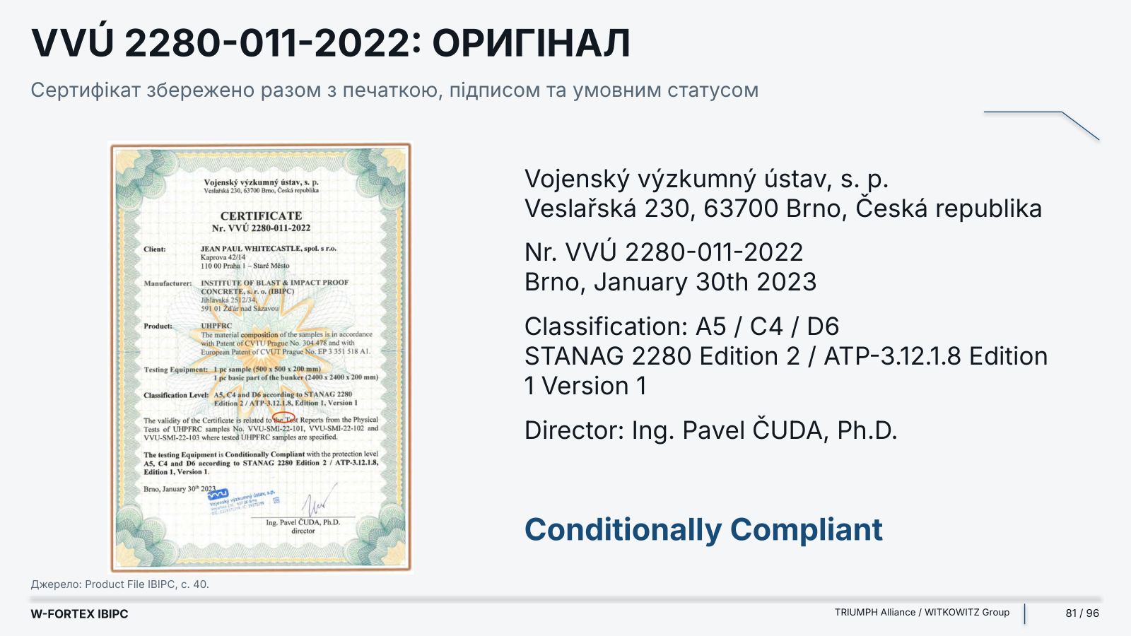
- Intellectual property — Patent CVUT Prague No. 304 478; European Patent EP 3 351 518 A1 (numbers from the certificate, p. 40)
- Limit — the descriptions of roles and supplies are Product File statements, not an independent registry check
Why high-performance concrete — engineering logic, not unconfirmed numerical advantages. The Product File contains no comparative percentages or universal reductions in cost, mass or thickness.
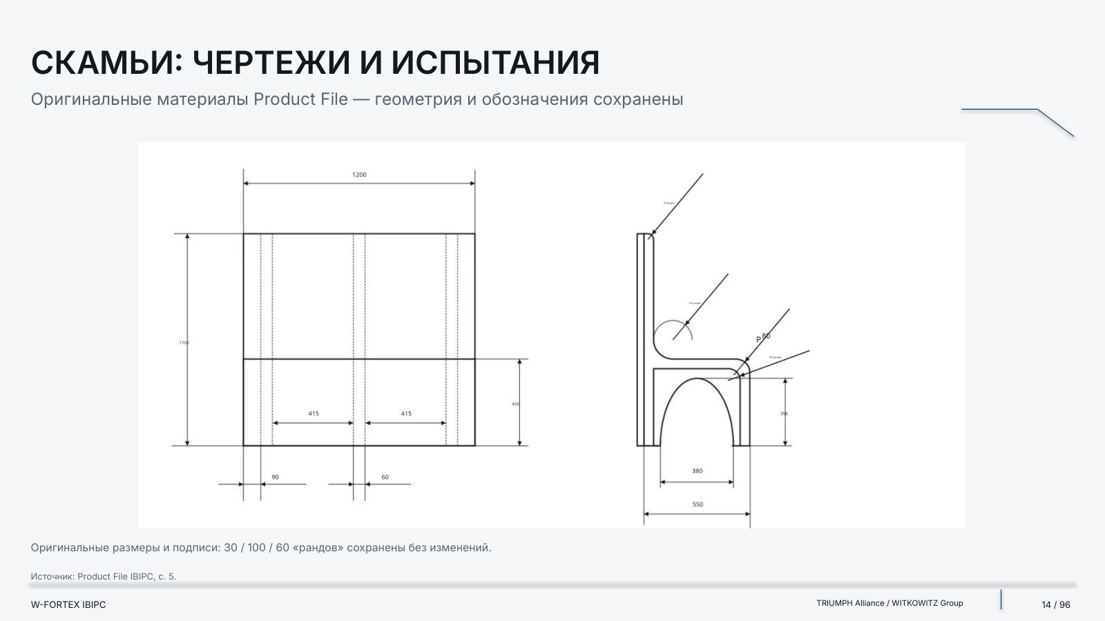
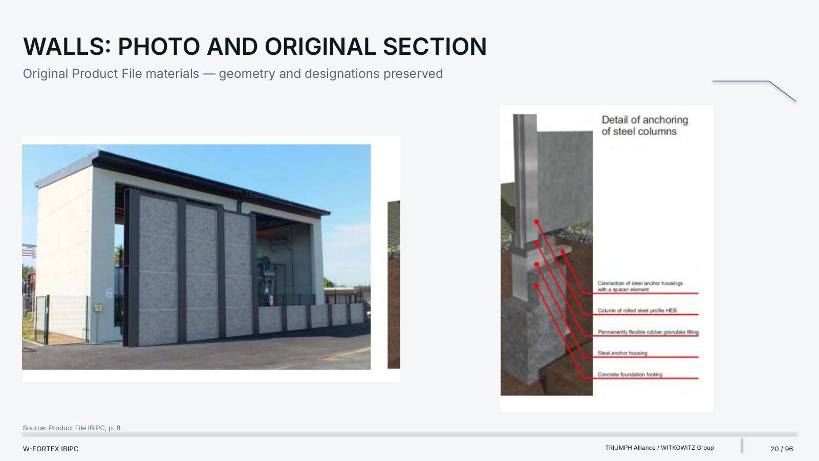
The catalogue’s numbering and names have been preserved, including repetitions. The catalogue claims 30 products but repeats numbers 10 and 20. For some items, individual characteristics are not provided.
| Parameter | Segment I | Segment II |
|---|---|---|
| Length, m | 2 | 2 |
| Internal W × H, m | 2 × 2.1 | 3 × 3 |
| Overall W × H, m | 2.4 × 2.5 | 3.4 × 3.4 |
| Wall thickness, m | 0.2 | 0.2 |
| Mass, t | 9.5 | 12.9 |
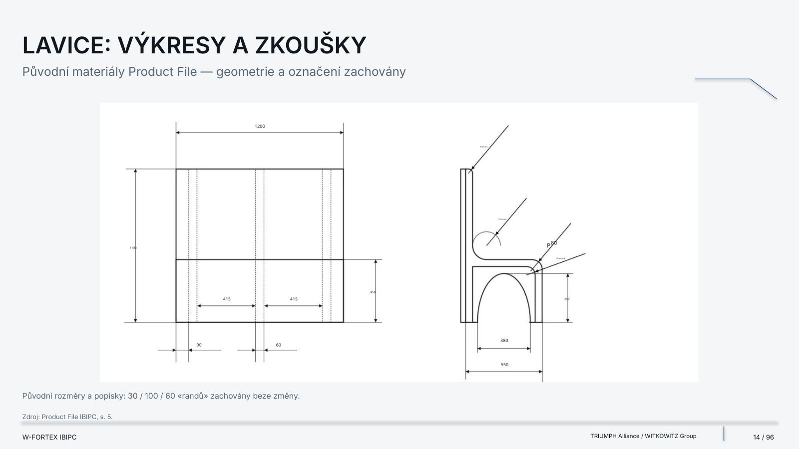
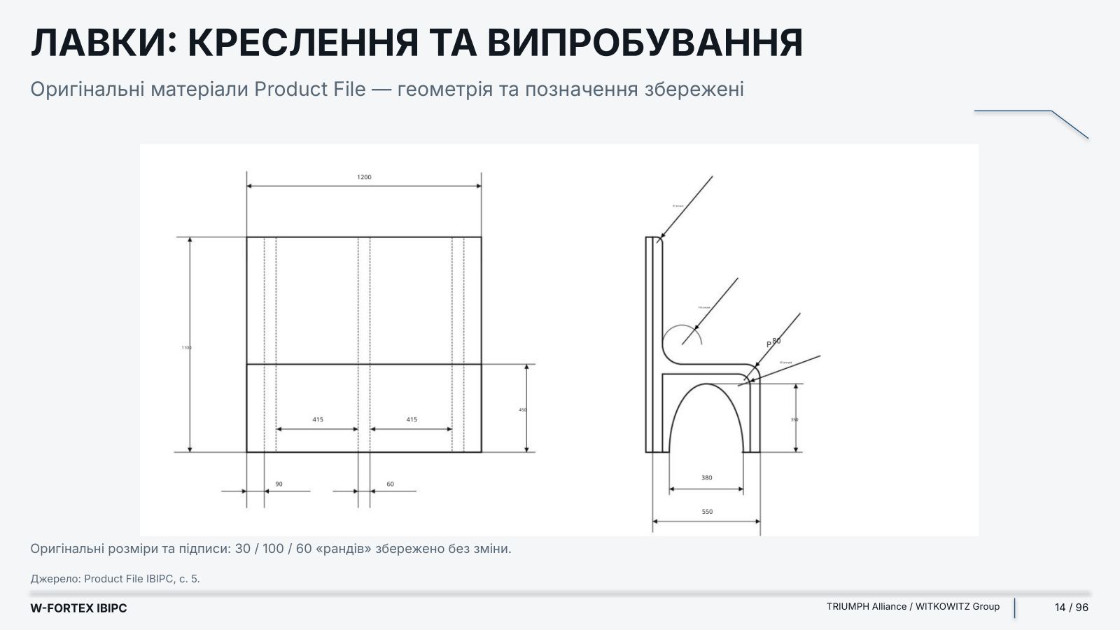
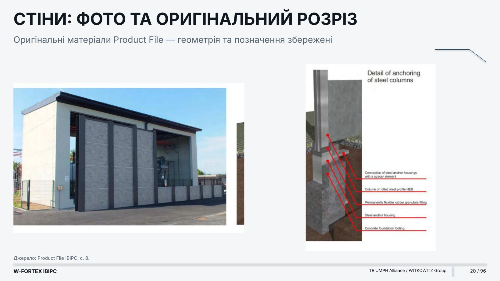
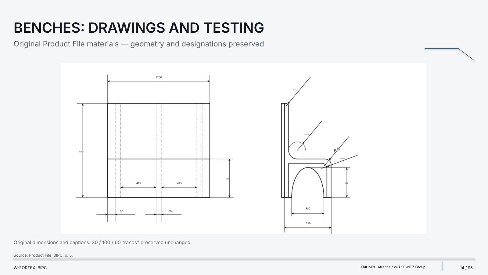
- Universal segments I / II — geometry, mass and a sealed locking joint with a rubber gasket; system material: UHPFRC; values per the catalogue, the drawing is not a scale template
- Where justified in the lower belt — zones with a limited footprint; high criticality and a high required level of protection; local areas where thickness and transport mass determine the layout
- What to combine with — Local RC; Gabion / Fill; Hybrid T/L; Hybrid T/Gabion; Steel; UHMWPE; Composite; Suspended Panels
- Local hardening — emergency and backup power; control, communications and monitoring; high-priority cable routes; local critical equipment zones
- Integration conditions — do not block ventilation, heat dissipation and emergency access; verify joints, openings, supports and foundation; do not transfer sample classes to a node without confirmation
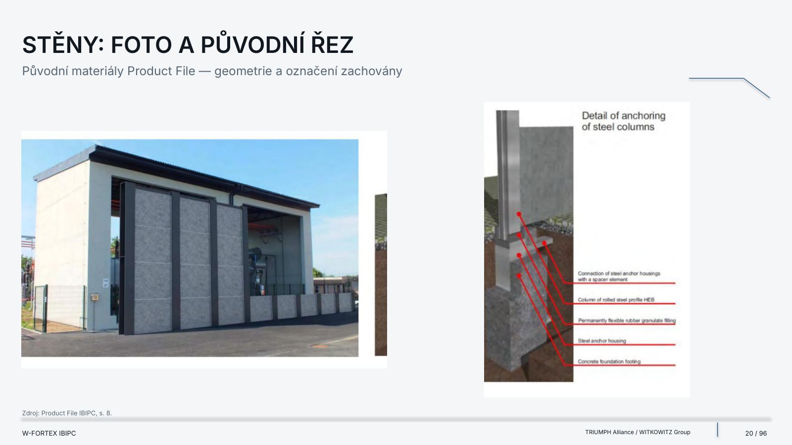
- Hybrid Wall — high-performance local fill / screen; compatibility with steel, RC, gabions and supports is verified separately
- T-Wall — a protective module or a local section of the belt; stability, base, joints, transport, installation
- Local shielding — a priority screen around a critical node; impact scenario, stand-off, openings, secondary effects
- Energy and industry — generators and cogeneration units; transformer and power nodes; power cables, optical fibre and IT / IoT; control points and backup systems
- Nuclear and radiological infrastructure — potential application within the W-FORTEX architecture; no automatic nuclear qualification is claimed; a separate safety justification, qualification and operator approval are required
- Logistics and economics — the cost of the material is assessed together with the full configuration: material + fabrication + delivery + crane + base + joints + installation, operation, repair, replacement and access to critical equipment
- Limit — the annex contains no invented percentages, costs, reductions in trips or universal savings
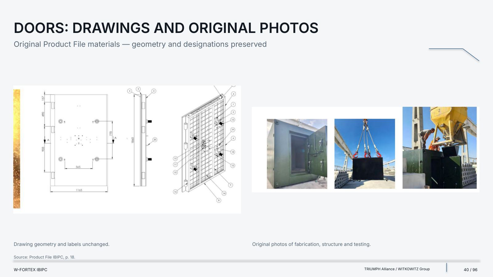
Technology. Modularity. A verified configuration. IBIPC is a high-performance option within W-FORTEX. Real drawings and results. Preserved documents. Open limits of evidence.
Material: Indicators Are Not Mixed
Catalogue parameters, concrete class and measured results are separate records. The supplied file contains no numerical data on flexural strength or mix composition. No assumed values have been added.
| Indicator | Source value | Origin / status |
|---|---|---|
| Compressive strength | 150 MPa | Catalogue, aircraft shelters, p. 27 |
| Tensile strength | 15 MPa | Catalogue, aircraft shelters, p. 27 |
| Compressive strength of mixes | Over 165 MPa | Catalogue, concrete mixes, p. 35 |
| High-strength concrete class | C105/115 · EN 206 | Catalogue, underground shelters, p. 20 |
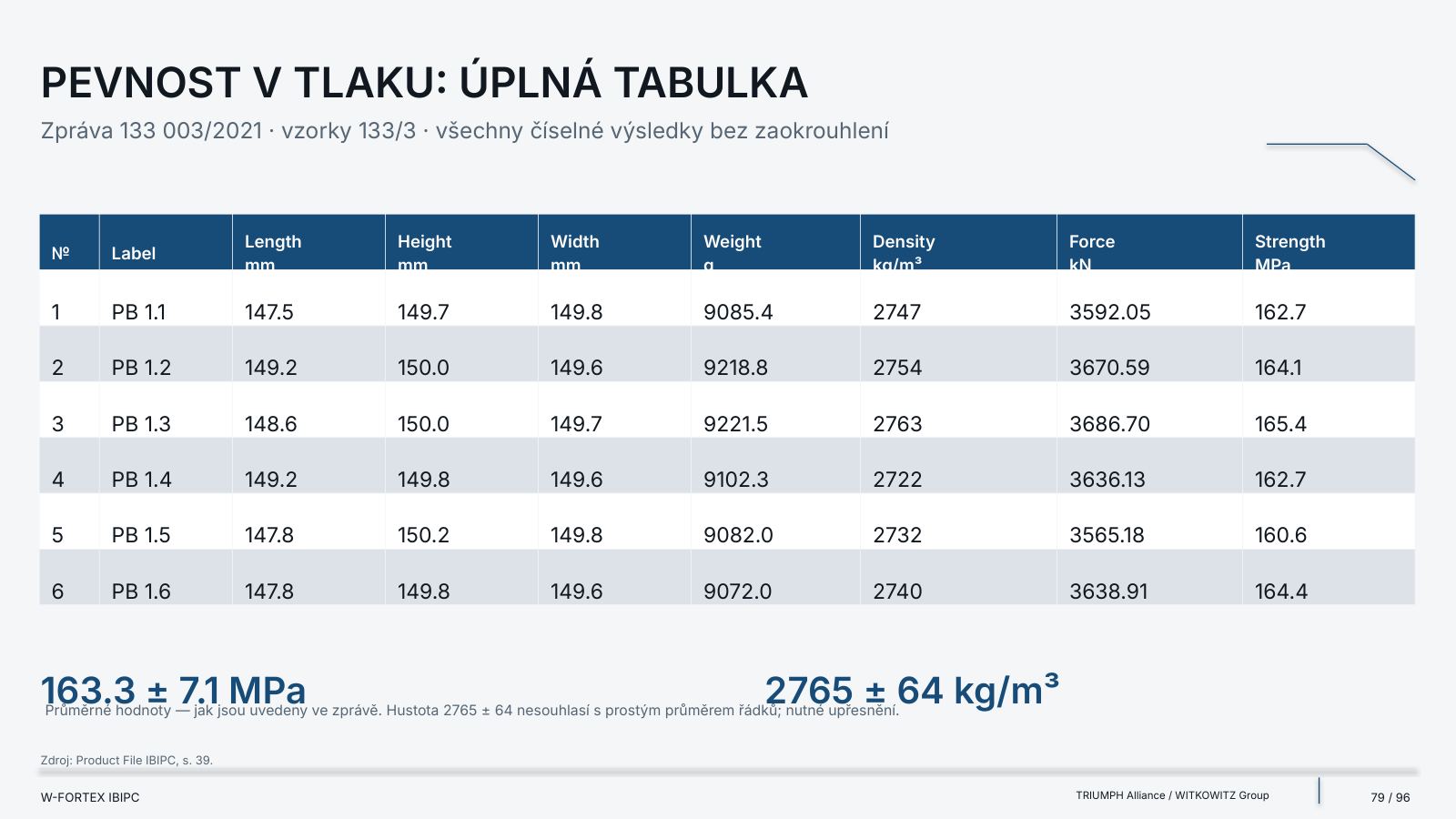
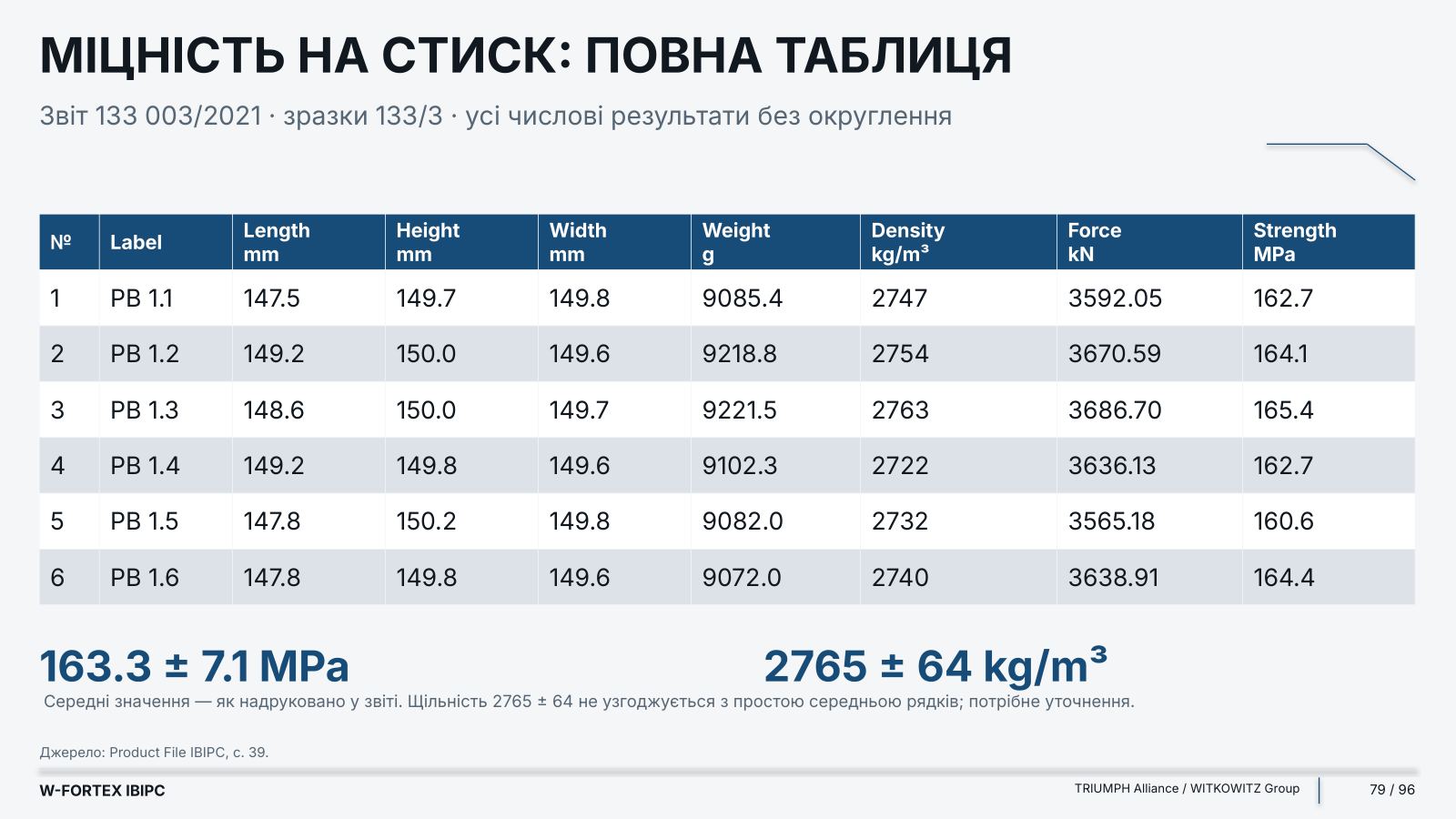
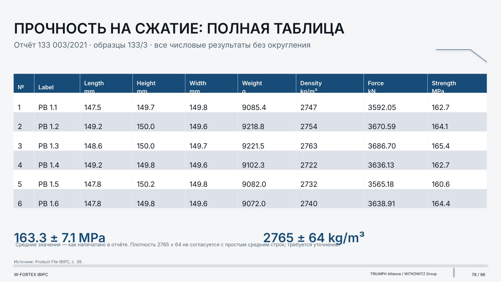
| Mean specimen strength | 163.3 ± 7.1 MPa | Report 133 003/2021, p. 39 |
| Mean density (as printed) | 2765 ± 64 kg/m³ | Report, p. 39; see the note on the discrepancy |
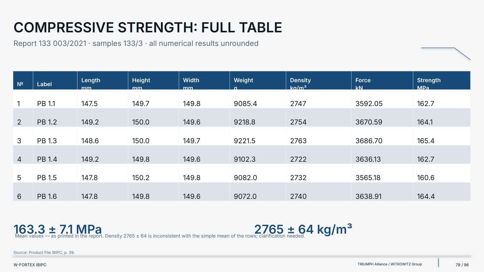
| No. | Label | Length, mm | Height, mm | Width, mm | Weight, g | Density, kg/m³ | Force, kN | Strength, MPa |
|---|---|---|---|---|---|---|---|---|
| 1 | PB 1.1 | 147.5 | 149.7 | 149.8 | 9085.4 | 2747 | 3592.05 | 162.7 |
| 2 | PB 1.2 | 149.2 | 150.0 | 149.6 | 9218.8 | 2754 | 3670.59 | 164.1 |
| 3 | PB 1.3 | 148.6 | 150.0 | 149.7 | 9221.5 | 2763 | 3686.70 | 165.4 |
| 4 | PB 1.4 | 149.2 | 149.8 | 149.6 | 9102.3 | 2722 | 3636.13 | 162.7 |
| 5 | PB 1.5 | 147.8 | 150.2 | 149.8 | 9082.0 | 2732 | 3565.18 | 160.6 |
| 6 | PB 1.6 | 147.8 | 149.8 | 149.6 | 9072.0 | 2740 | 3638.91 | 164.4 |
| Mean values | 2765 ± 64 | 163.3 ± 7.1 |
Mean values — as printed in the report. The density of 2765 ± 64 does not agree with the simple mean of the rows; clarification is required.
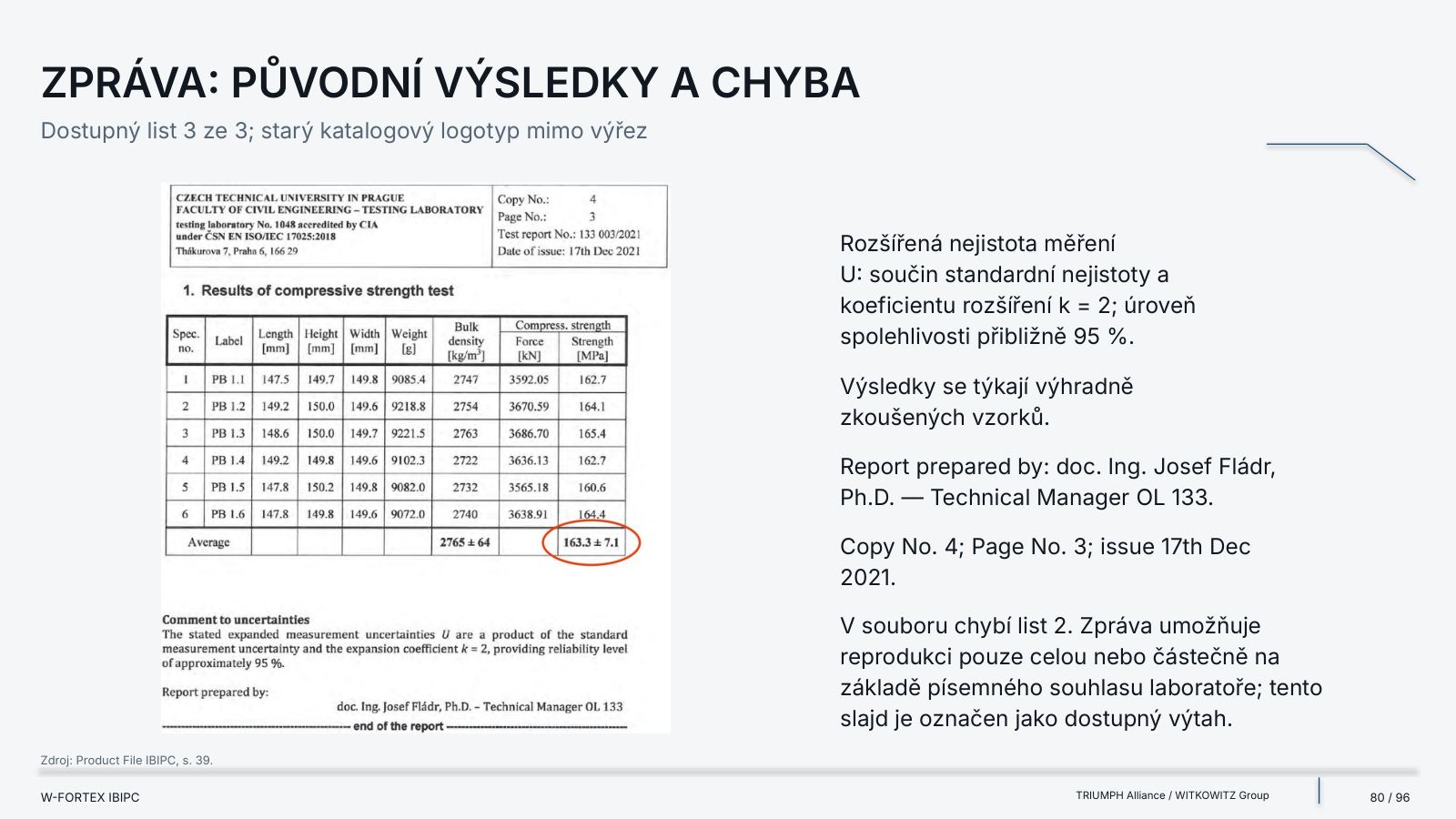
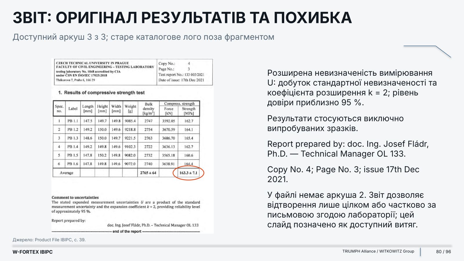
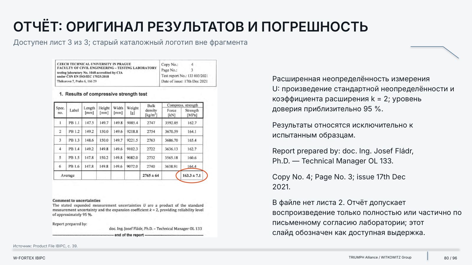
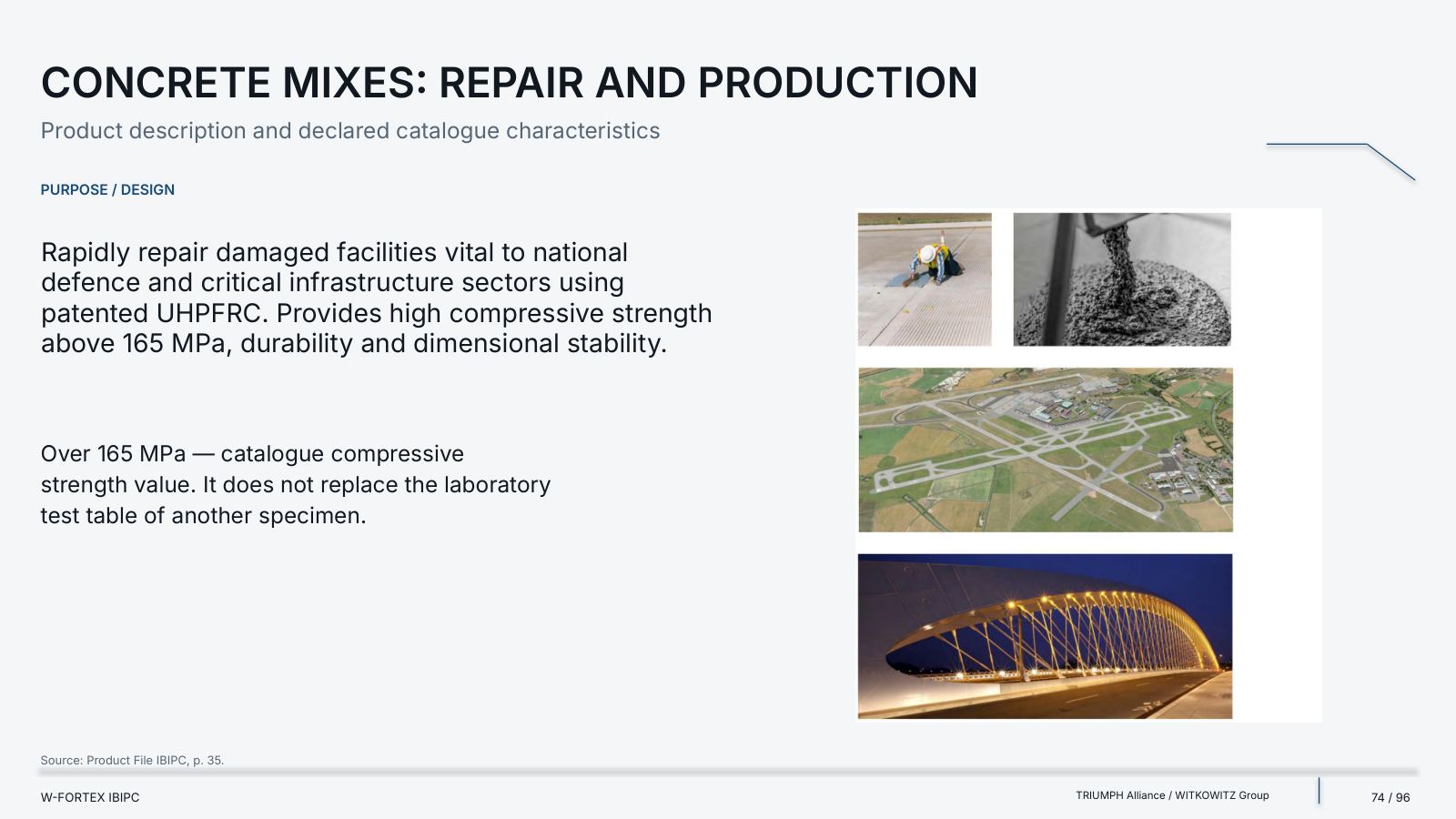
- Laboratory report — Czech Technical University in Prague, Faculty of Civil Engineering · Testing Laboratory 1048; Expert laboratory OL 133
- Accreditation — CIA · ČSN EN ISO/IEC 17025:2018
- Subject / date — Compressive strength of test specimens 133/3 · 17th December 2021
- Scope — sheets 1 and 3 are available; sheet 2 is missing; this is an available extract, not the full report
- Uncertainty — expanded uncertainty U: k = 2, confidence level approximately 95 %
- Limit — the results apply only to the specimens tested
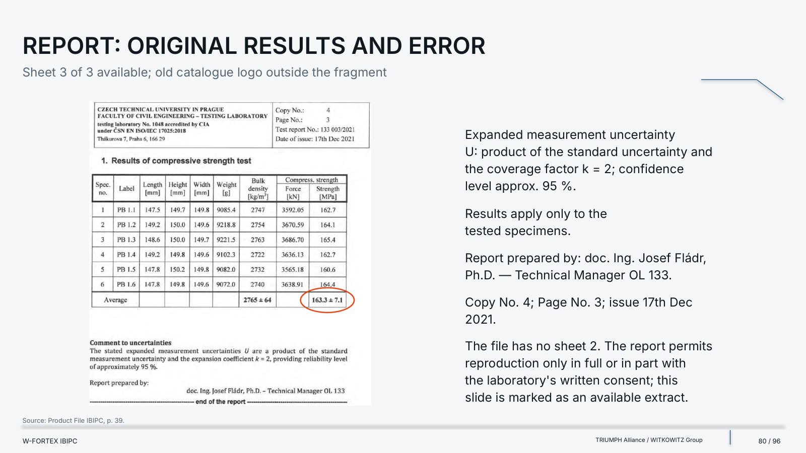
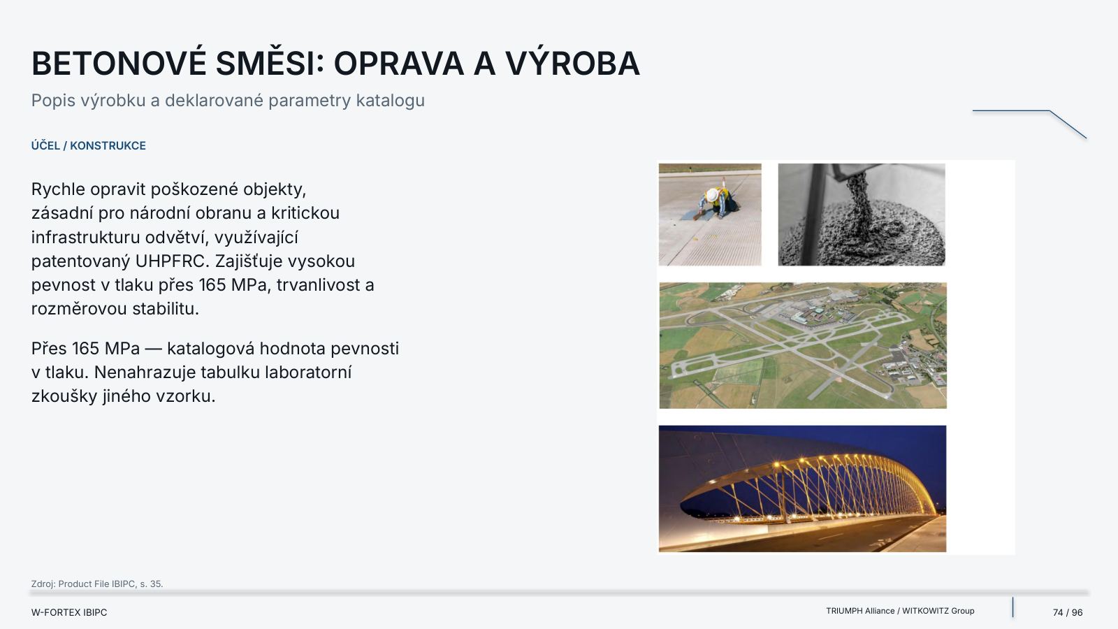
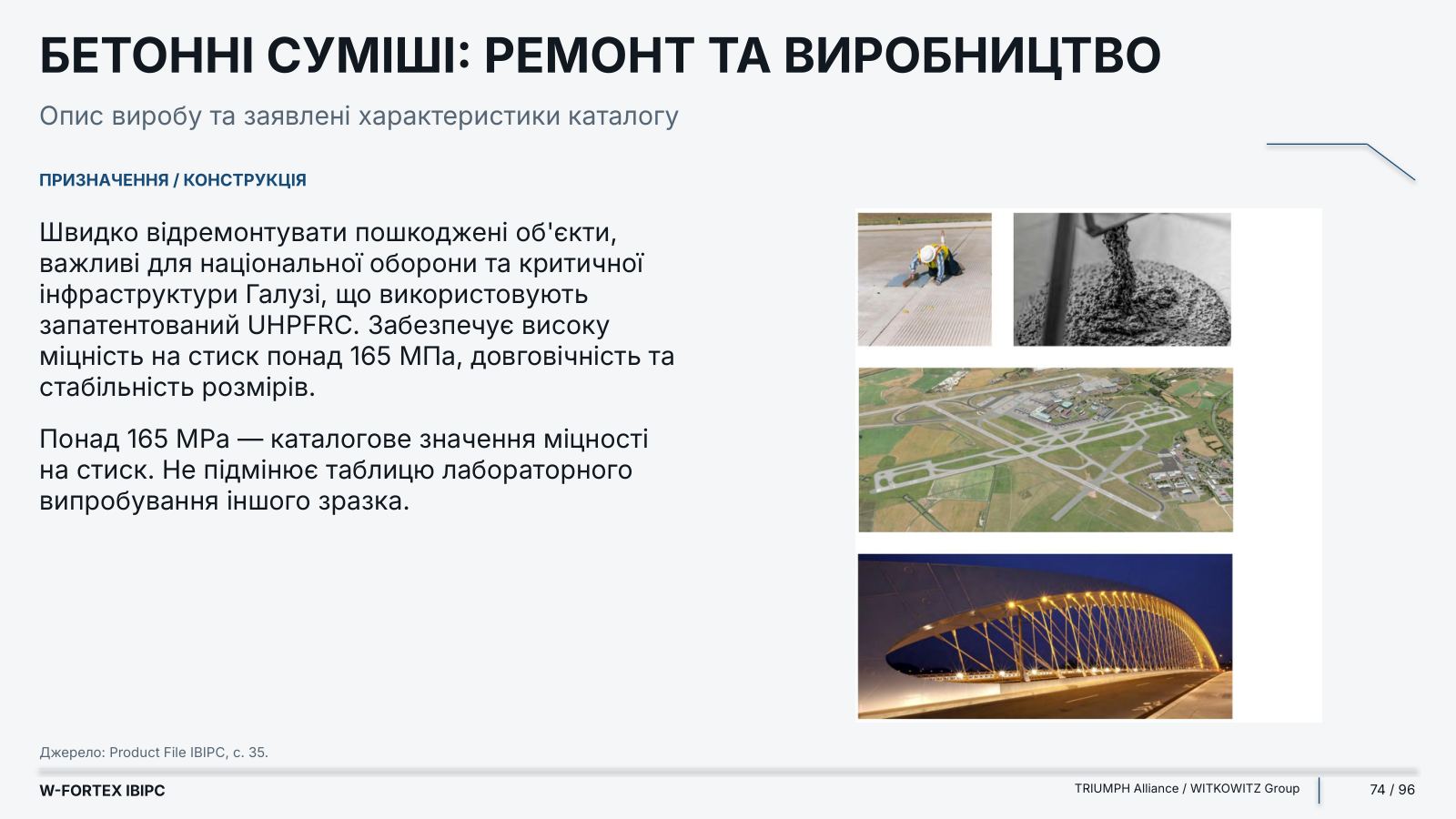
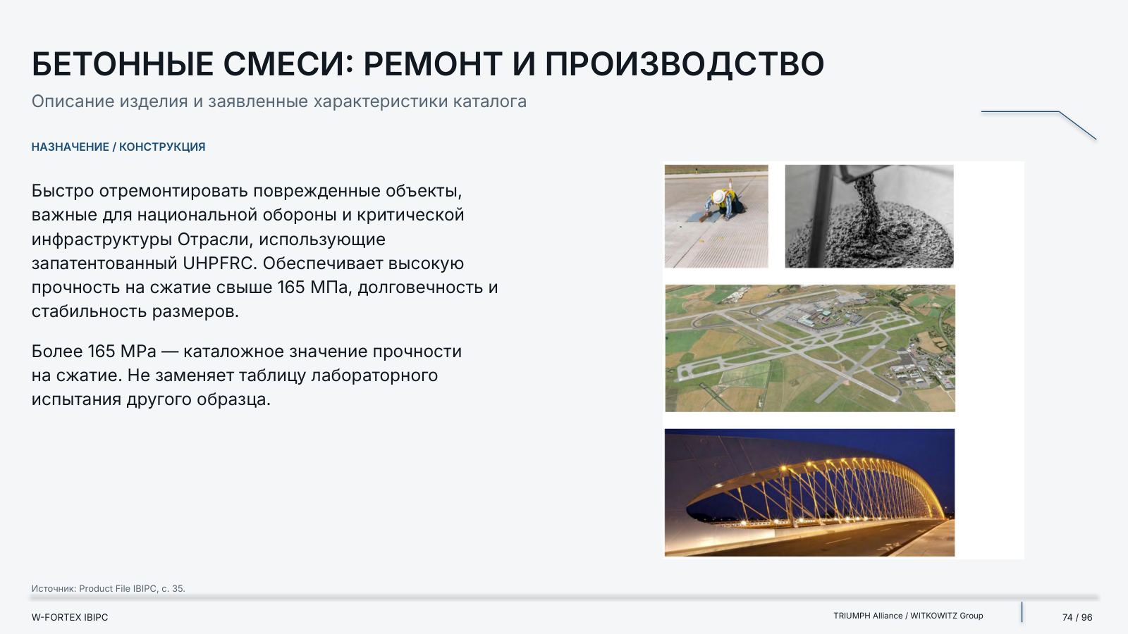
- Concrete mixes: repair and production — rapid repair of damaged facilities important for national defence and critical infrastructure
- Claimed in the catalogue — high compressive strength of over 165 MPa, durability and dimensional stability
- Limit — over 165 MPa is a catalogue value; it does not replace the laboratory test table of another specimen
- Finishing and camouflage — the surface of the elements is treated with UNIVERSUM CAMOUFLAGE PATTREN primer; on request — eight other camouflage colours
- Catalogue reference — NATO MERDEC; the PATTREN / MERDEC designations are preserved as printed
- Colours — summer green · winter green · snow with trees · snow with open ground · tropical green · Rerd desert · grey desert · winter Arctic
STANAG / NATO: Evidence, Limits and a Map of Primary Records
Each statement is tied to a specific document. The W-FORTEX concept is not nuclear qualification and not a new test result; NATO supplier status does not mean certification of every product.
| Record | Exact designations | Status |
|---|---|---|
| Catalogue class A5 | 14.5 × 114 API M32 | STANAG 2280:2016 Edition 2 |
| Ballistic glass / crew protection | STANAG 4569 Level IV | Catalogue claim for bunkers / shelters / checkpoints |
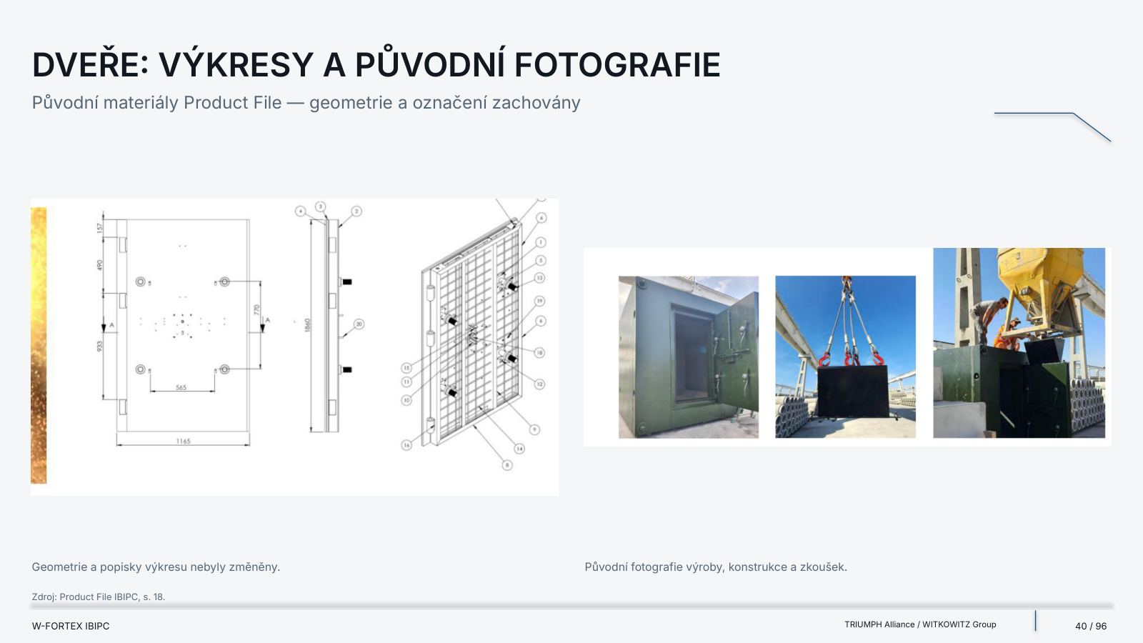
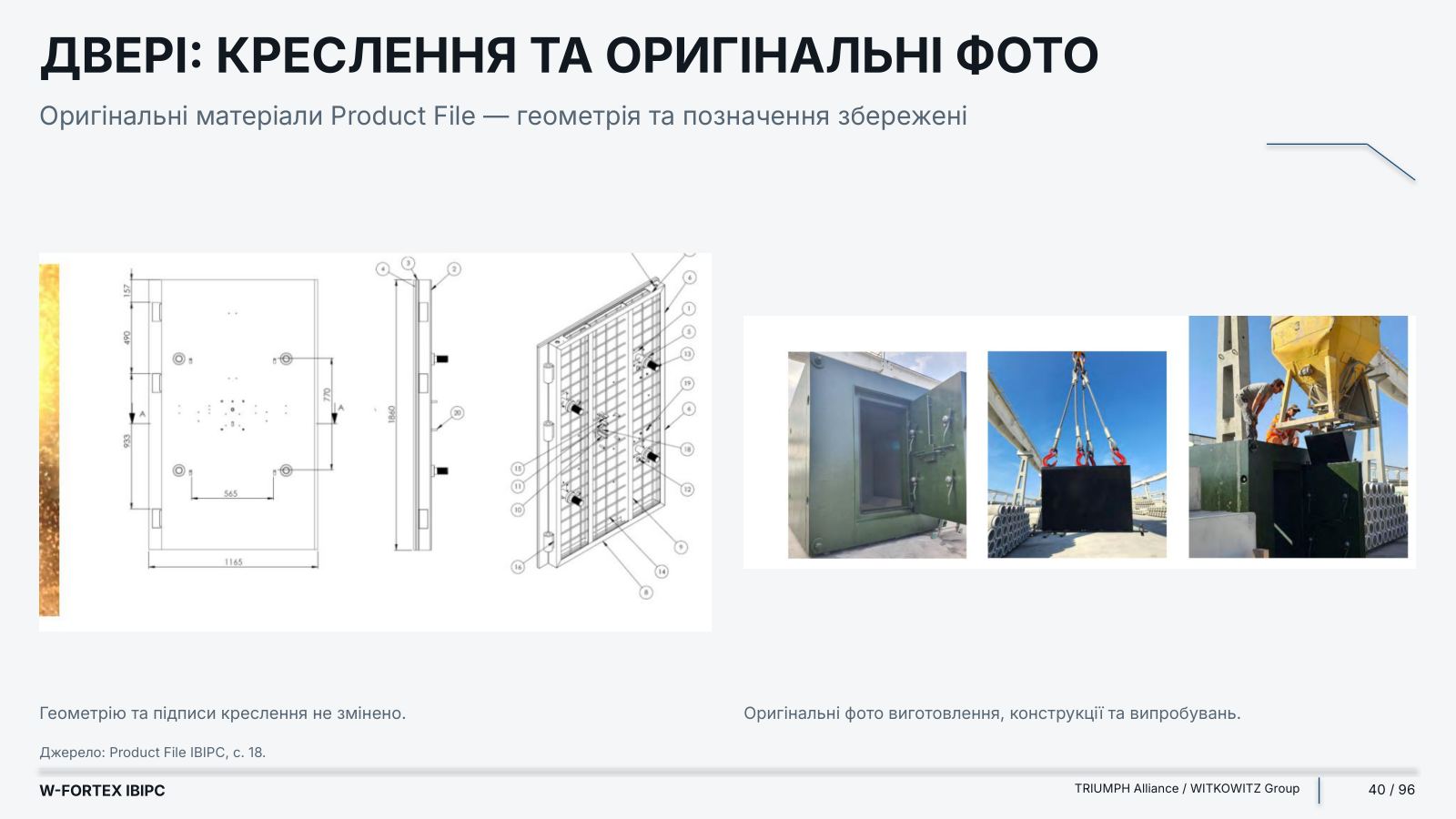
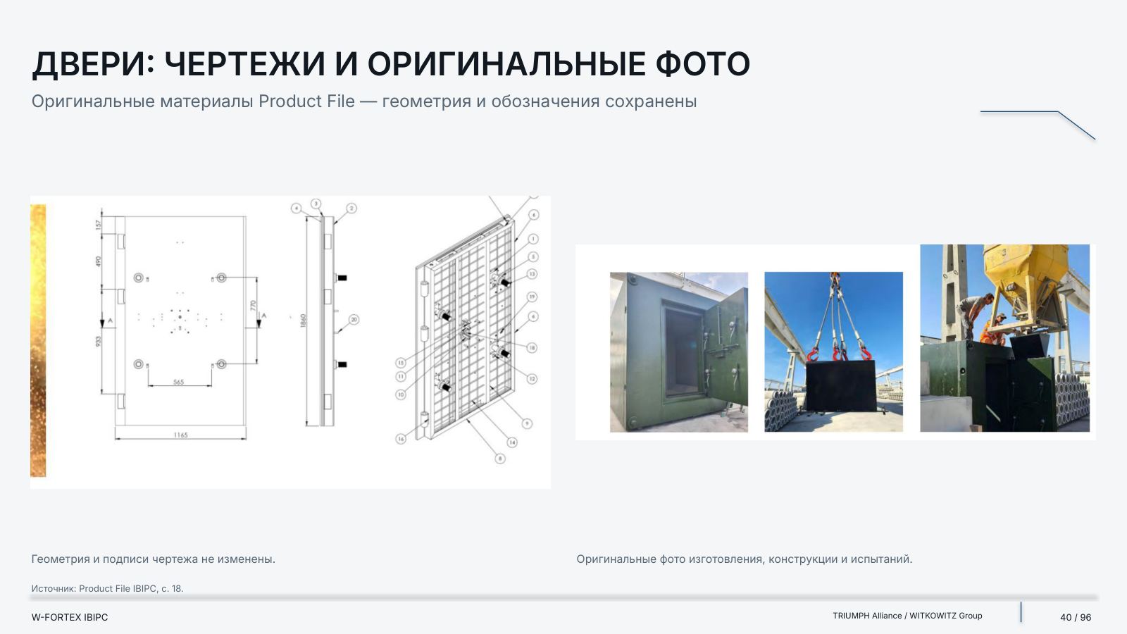
| Doors, list of ammunition | 7.62 × 54 R API; 7.62 × 51 AP8 (WC); 12.7 × 99 API M8; 14.5 × 114 API | Sandwich doors, p. 18 |
| Test description | 12.7 × 99 API M8 / 14.5 × 114 API M32 · impact velocity 900 m/s | Description p. 42; armour-piercing incendiary ammunition |
Ballistic protection: the source does not provide a universal ballistic test distance or all the setup details for every product.
| Origin | Value | Limit of interpretation |
|---|---|---|
| Catalogue, class C4 | 107-mm rocket / 120-mm mortar | Claimed fragmentation-effect class |
| Catalogue, class D6 | 50 kg TNT | Do not equate with the 20 kg test |
| Test description, p. 42 | 107 mm / 120 mm · distance 1.5 m | Not a full test report |
| Blast test description, p. 42 | 20 kg TNT · distance 5 m | A separate scenario as stated |
| Photos / captions of bunker tests | 120-mm mortar: explosion on the bunker roof | pp. 15, 21, 26; original photos preserved |
Blast and fragments are different configurations. The supplied Product File contains no numerical overpressure values in kPa for these tests.
| Document / record | Details | What the source confirms |
|---|---|---|
| Catalogue registration | BUNKR IBIPC · S-22802016; 0145410000544 · A492H04BAYR6 | Catalogue claim, p. 9 |
| Ministry of Defence letter | 490537/2024-1216 · 17 June 2024; NCAGE 8286G · NSN 5411160090335 | Recommendation / reference letter |
| Laboratory report | 133 003/2021 · 17 December 2021 | Compression test; sheets 1 and 3 available |
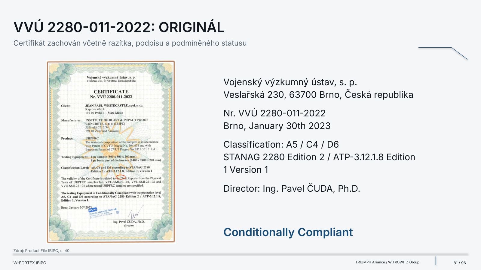
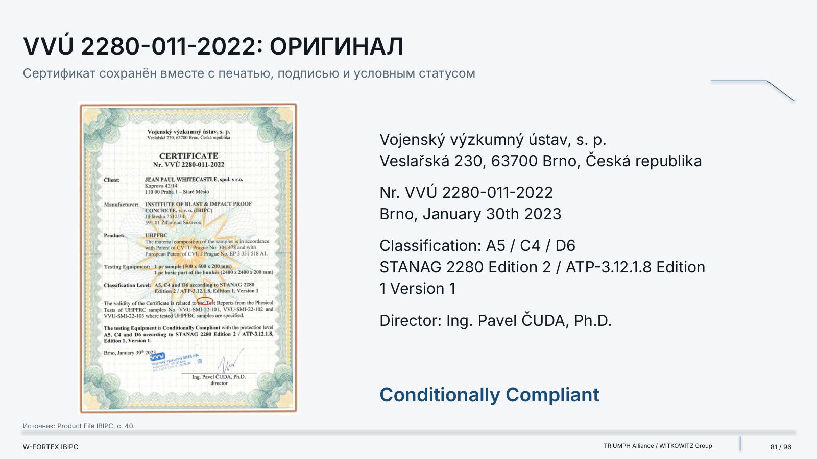
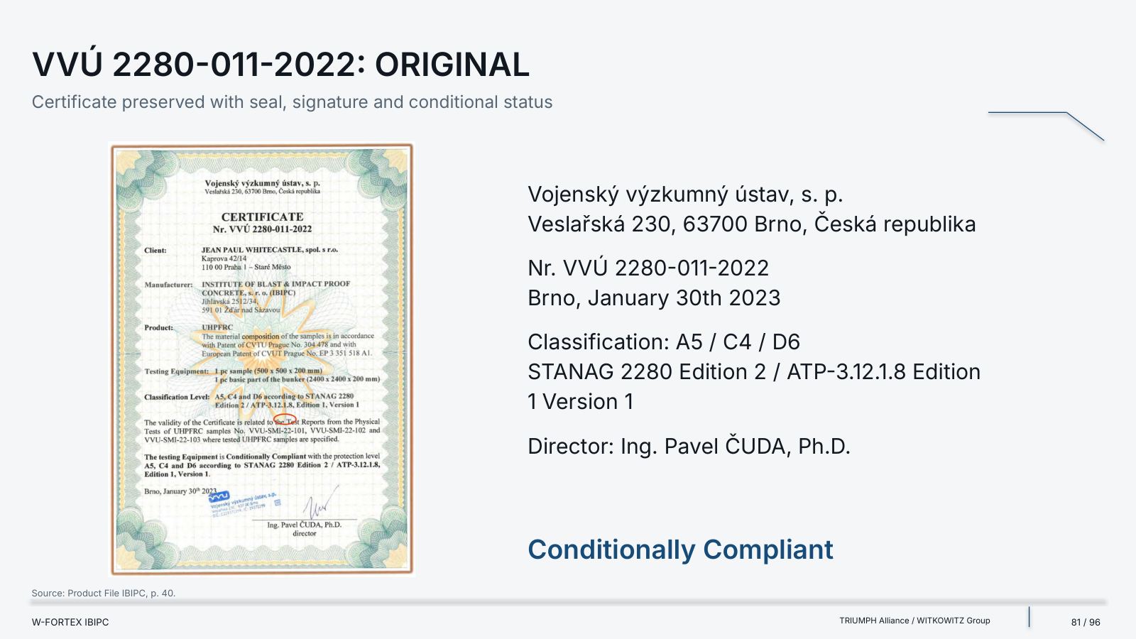
| VVÚ certificate | VVÚ 2280-011-2022 · 30 January 2023 | A5 / C4 / D6; Conditionally Compliant |
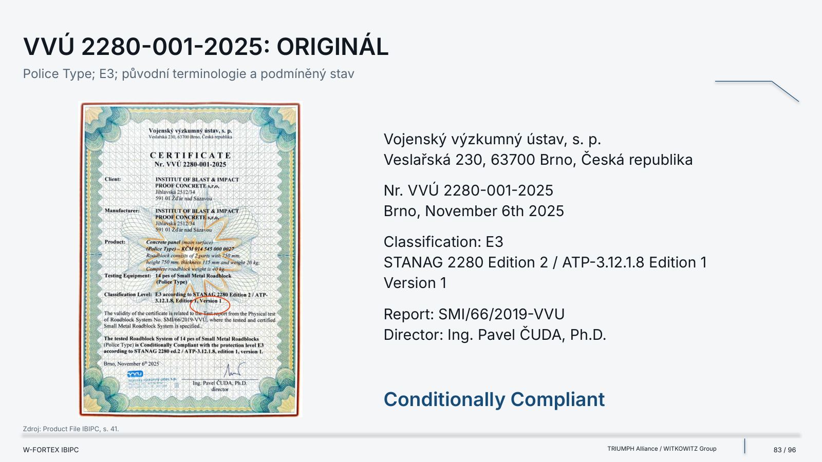
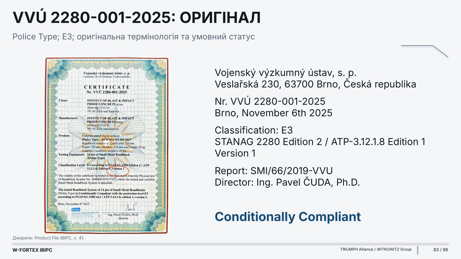
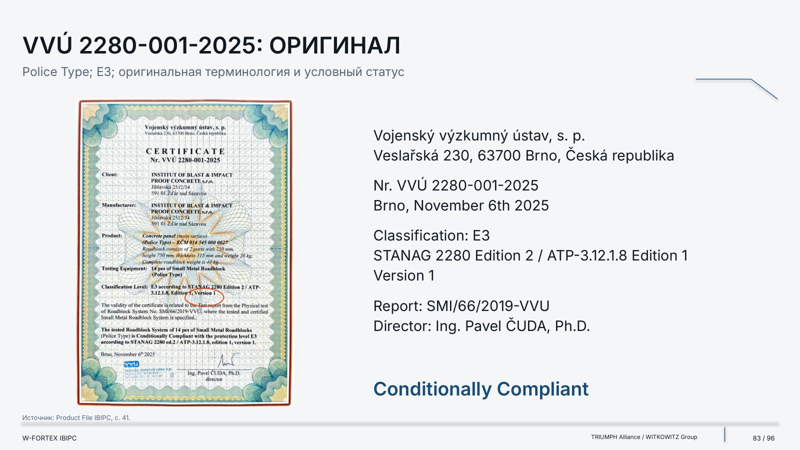
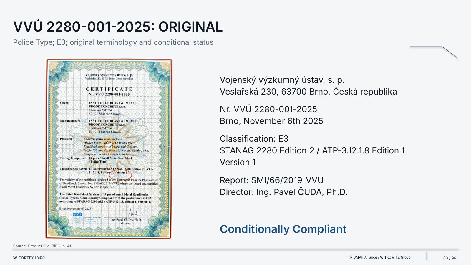
| VVÚ certificate | VVÚ 2280-001-2025 · 6 November 2025 | E3; Conditionally Compliant |
| Type | What it means | What it does not mean |
|---|---|---|
| Catalogue claim | The manufacturer’s description, a claimed class or property | Not a universal guarantee for every configuration |
| Test result | Data for a specific specimen and test conditions | Not transferable to any sizes and structures |
| Certificate / letter | A defined product, configuration, details and status | Not blanket certification; conditions remain |
| W-FORTEX concept | The place of the technology in the system architecture | Not nuclear qualification and not a new test result |
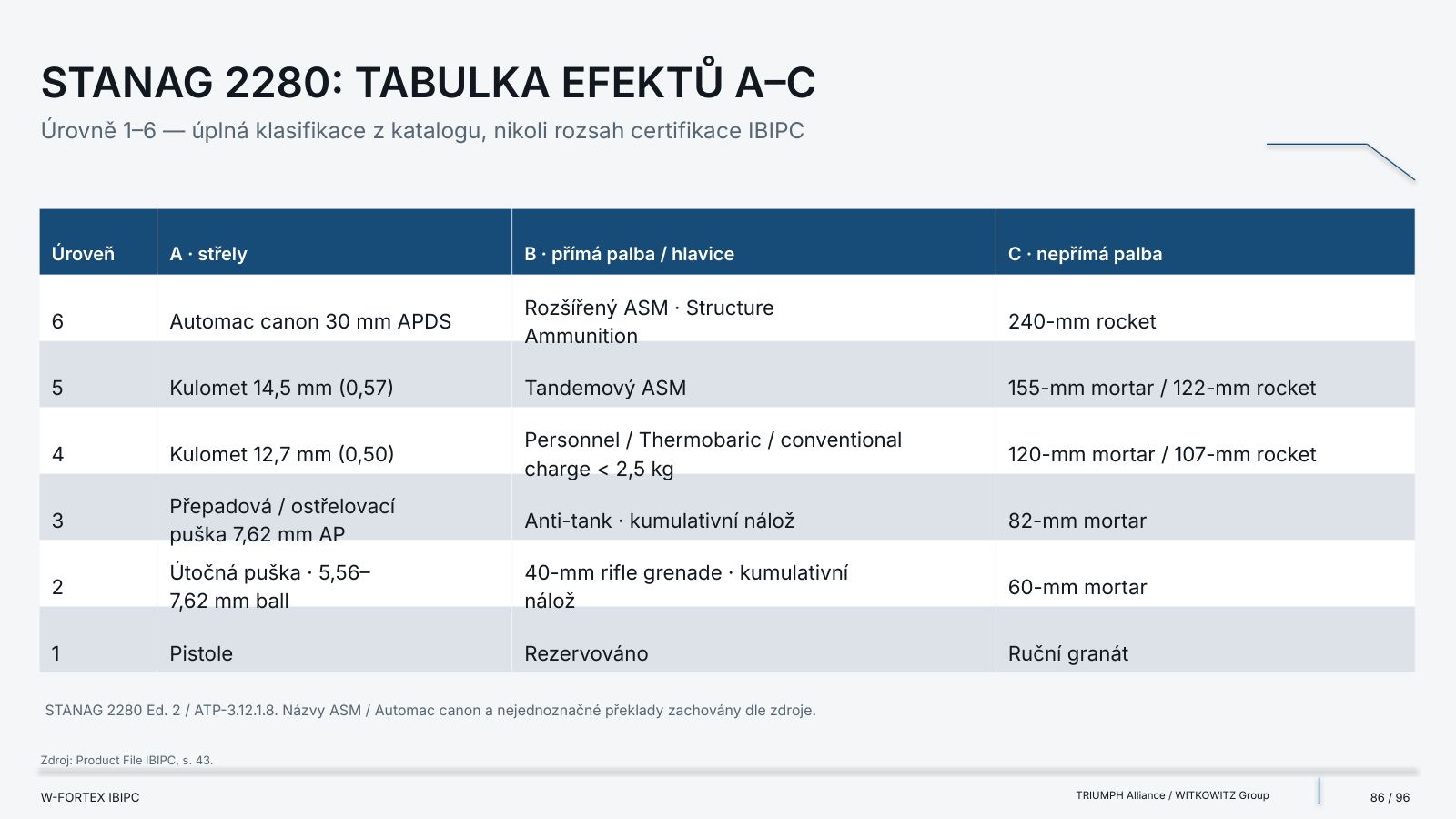
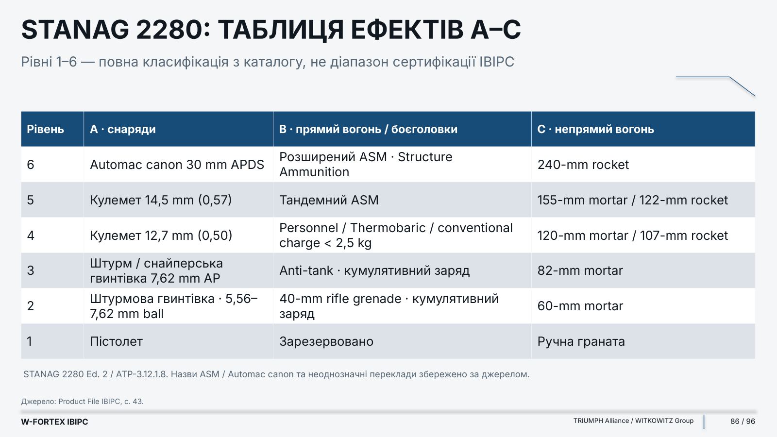
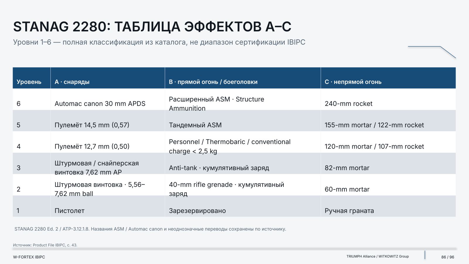
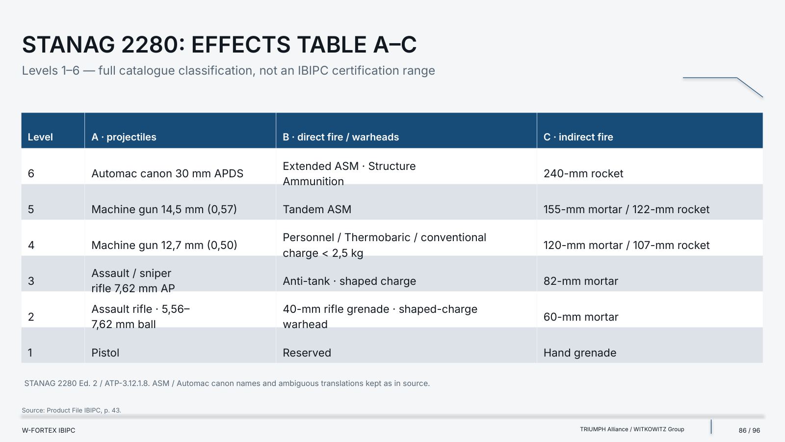
| Level | A · projectiles | B · direct fire / warheads | C · indirect fire | D · high explosive (TNT-eq.) | E · vehicles |
|---|---|---|---|---|---|
| 6 | Automac canon 30 mm APDS | Advanced ASM · Structure Ammunition | 240-mm rocket | 50 kg | Tracked vehicle |
| 5 | 14.5 mm machine gun (0.57) | Tandem ASM | 155-mm mortar / 122-mm rocket | 10 kg | Large truck · 32,000 kg |
| 4 | 12.7 mm machine gun (0.50) | Personnel / Thermobaric / conventional charge < 2.5 kg | 120-mm mortar / 107-mm rocket | 2 kg | Truck · 7500 kg |
| 3 | 7.62 mm AP assault / sniper rifle | Anti-tank · shaped charge | 82-mm mortar | 1 kg | Small truck · 2500 kg |
| 2 | Assault rifle · 5.56–7.62 mm ball | 40-mm rifle grenade · shaped charge | 60-mm mortar | 0.5 kg | Passenger car · 1500 kg |
| 1 | Pistol | Reserved | Hand grenade | 0.1 kg | Motorcycle |
STANAG 2280 Ed. 2 / ATP-3.12.1.8: levels 1–6 — the full classification from the catalogue, not the IBIPC certification range. The ASM / Automac canon names and ambiguous translations are preserved per the source. The ATP covers impact on infrastructure: blast; penetration; fragmentation; secondary effects, including spalling and fire.
| Source records | What needs clarification |
|---|---|
| A5 / C4 / D6 ↔ A5 / D4 / D6 | Catalogue / 2022 certificate ↔ Ministry of Defence letter |
| 20 kg TNT at 5 m ↔ D6 / 50 kg TNT | A separate test description ↔ the claimed class |
| 150 MPa; over 165 MPa; 163.3 ± 7.1 MPa | Different sources / specimens; not a single guaranteed indicator |
| 2765 ± 64 kg/m³ | Printed mean density ↔ arithmetic of the rows |
| 0.58 m³; “million tonnes” | A light version of the pyramid and a machine translation of the unit |
| 1.8 Pa | The ventilation entry requires a primary specification |
| Concrete panel ↔ Small Metal Roadblock | Ambiguous names in the Police Type certificate |
| E3 ↔ E2 / 1500 kg marked in the table | Do not reconcile the certificate and the catalogue highlighting by assumption |
| Report: sheets 1 and 3; sheet 2 missing | An available extract, not the full report |
- Letter from the Ministry of Defence of the Czech Republic — No. 490537/2024-1216 · 17th June 2024; INSTITUTE OF BLAST & IMPACT PROOF CONCRETE, s.r.o. — a contractual partner of the Ministry of Defence
- Classes in the letter — testing and certification by the Military Research Institute under NATO STANAG 2280:2016 Ed. 2; the letter itself states classes A5, D4, D6
- Identifiers — NCAGE 8286G; NSN 5411160090335; 13-digit NATO STOCK NUMBER
- Claims of the letter — drone attacks; infantry weapons fire up to 14.5 mm; artillery rounds up to 155 mm; explosions near objects up to 50 kg TNT; grenades
- Limit — these are statements of the letter, not full reports for every scenario; a recommendation and NATO supplier status are not blanket product certification
- Claimed in the Product File — high compressive strength of 150 MPa and tensile strength of 15 MPa, classes A5, C4, D6, zero radio-wave transmission, a very high level of infrared shielding and extremely high nuclear shielding properties
- What the file does not establish — attenuation coefficients, spectrum, thickness for a given dose, test regime or nuclear qualification are not provided
- A5 / C4 / D6 — are not radiation protection classes
- RF / IR / gamma / neutron shielding — requires a separate justification for the specific configuration
- Catalogue claims regarding WMD / nuclear explosion — are not automatic nuclear qualification
- VVÚ certificate 2280-011-2022 — Classification A5 / C4 / D6; STANAG 2280 Edition 2 / ATP-3.12.1.8 Edition 1 Version 1; Conditionally Compliant
- VVÚ certificate 2280-001-2025 — Classification E3; Report SMI/66/2019-VVU; Conditionally Compliant; Concrete panel and Small Metal Roadblock (Police Type) — ambiguity preserved
W-FORTEX pilot configuration request
Describe the facility, its critical functions and threat profile. Next step: facility analysis → requirements → technology selection → interface verification → pilot.
From a Complete Programme to a Pilot Configuration
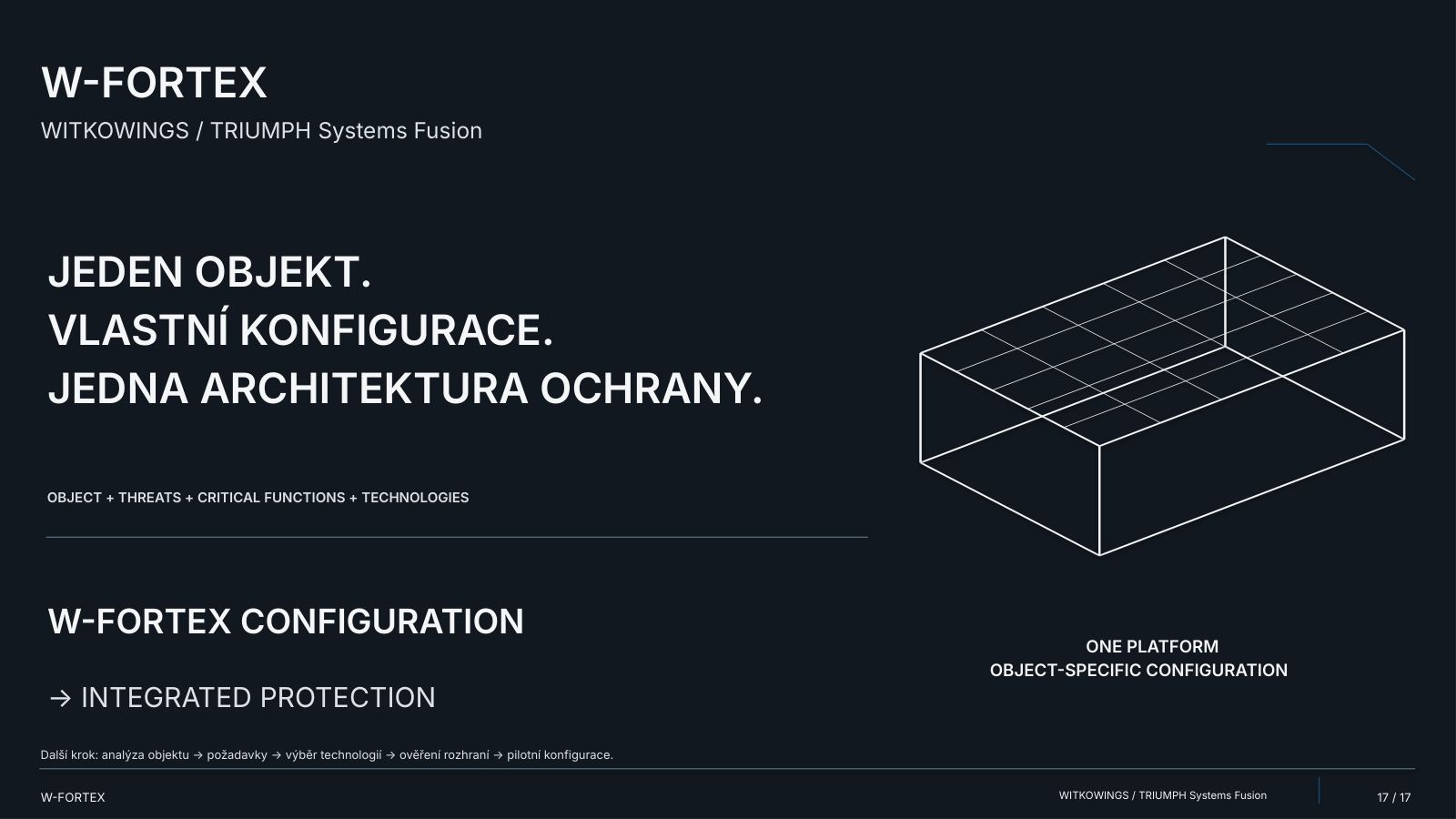
Protect the facility: an independent physical perimeter, selected layers and local hardening. Preserve people: shelters and life support, specialised protected modes. Sustain the function: energy · control · communications, autonomy and recovery. One facility. Its own configuration. A shared goal — continuity. Facility analysis → requirements → technology selection → interface verification → pilot. Project integration, qualification and safety justification — for the specific facility and scenario.
Full programme — 152 slides (EN V1). The programme concept is not certification. IBIPC evidence applies only to the relevant products and test conditions.